SCAMP Centerboard:
• I calculated area and depth required to pour 10lbs of lead in each half of the centerboard
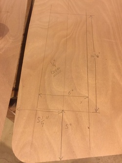
• Based on 0.41lbs/cubic inch I decided to go with a cavity of 0.25”x6”x16.375” in each half. This is rounding up a bit, as I planned to fill any remaining void with epoxy.
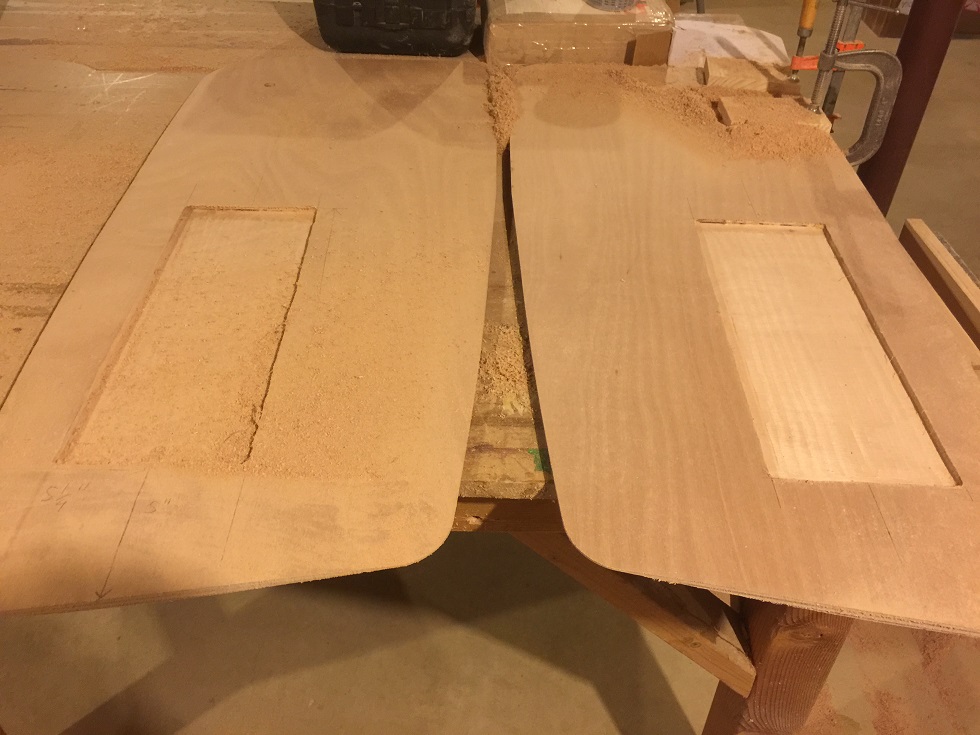
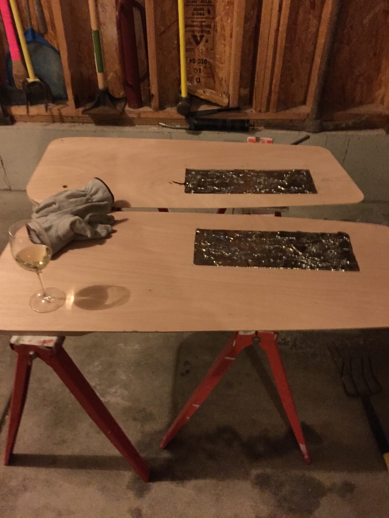
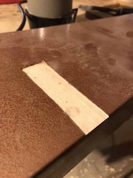
• Drew lines on each half of center board for cavity
• Used router to create the cavity in each side. I did not use a template or guide; just moved the router by hand, as I figured this was an internal cavity to be filled with lead and epoxy, and at such a low routing depth, very good manual accuracy can be attained.
• Based on 0.41lbs/cubic inch I decided to go with a cavity of 0.25”x6”x16.375” in each half. This is rounding up a bit, as I planned to fill any remaining void with epoxy.
• Drew lines on each half of center board for cavity
• Used router to create the cavity in each side. I did not use a template or guide; just moved the router by hand, as I figured this was an internal cavity to be filled with lead and epoxy, and at such a low routing depth, very good manual accuracy can be attained.
• Weighed 20lbs of lead, and threw in a bit over 20lbs by adding some sinkers, to account for lead that might remain in the melting
pot.
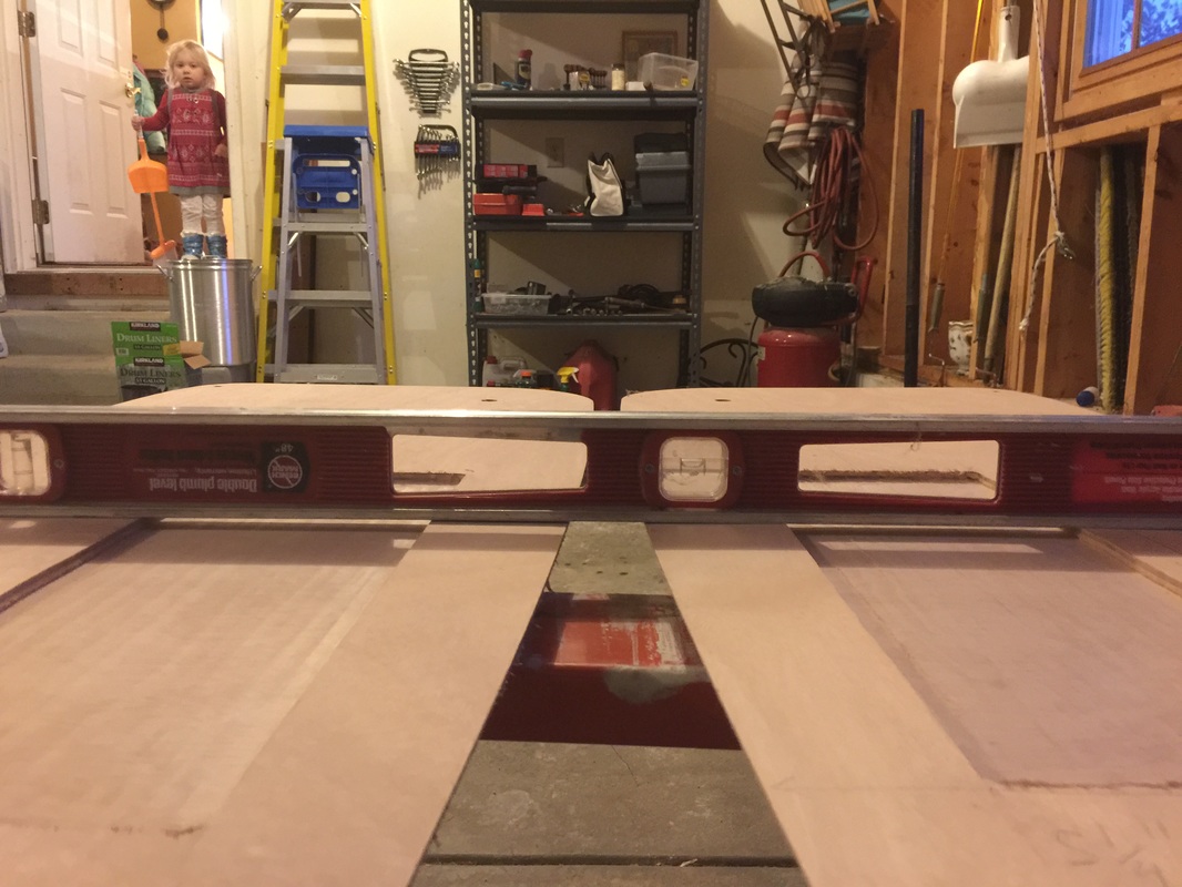
• Leveled the centerboard pieces in both directions
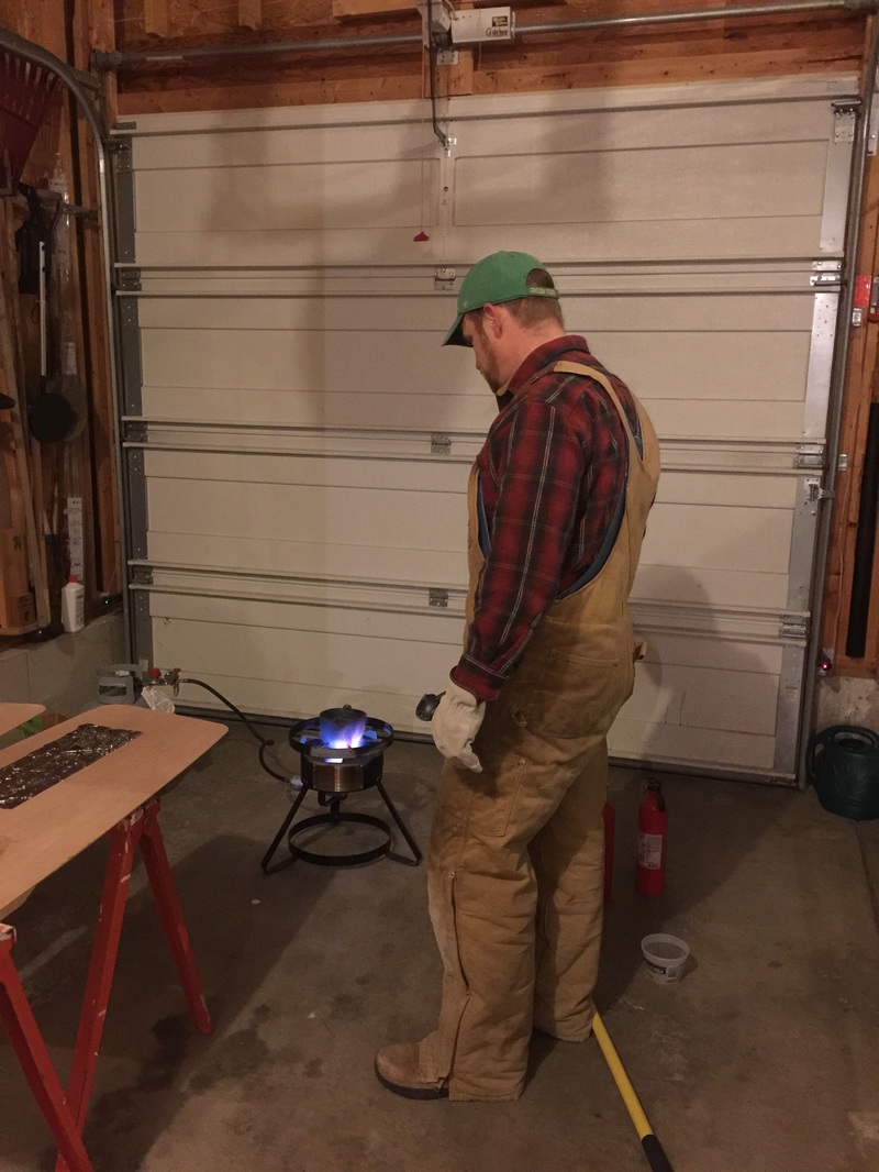
• Right around 0degF outside, chilly day!
• Propane stove melted lead fast, maybe 8 minutes to start melting, and once the pot was hot the new lead that I added melted
quicker than that.
•20lbs capacity cast lead melting pot was used.
pot.
• Leveled the centerboard pieces in both directions
• Right around 0degF outside, chilly day!
• Propane stove melted lead fast, maybe 8 minutes to start melting, and once the pot was hot the new lead that I added melted
quicker than that.
•20lbs capacity cast lead melting pot was used.
- I had 3lbs of lead left because the lead cooled so fast that I couldn't get the pour perfectly level (0degF temps outside the garage, with the other garage door open for ventilation didn't help it run smooth). So I added about 2.5" x 4.5" of 1/4" depth cavity per side and filled those with the remaining lead. 20lbs of lead poured.
- Then poured unthickened epoxy all around any voids over and between the lead and the routed cavity. Let cure overnight.
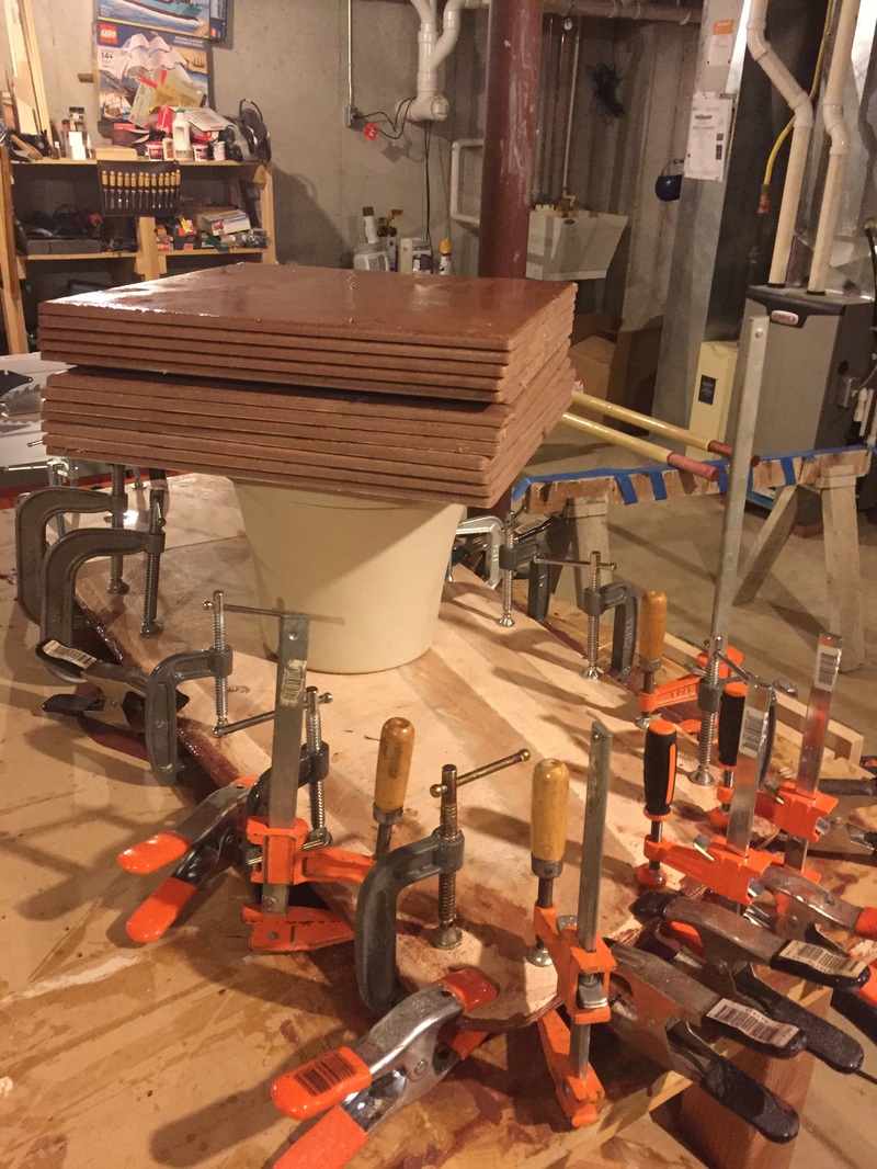
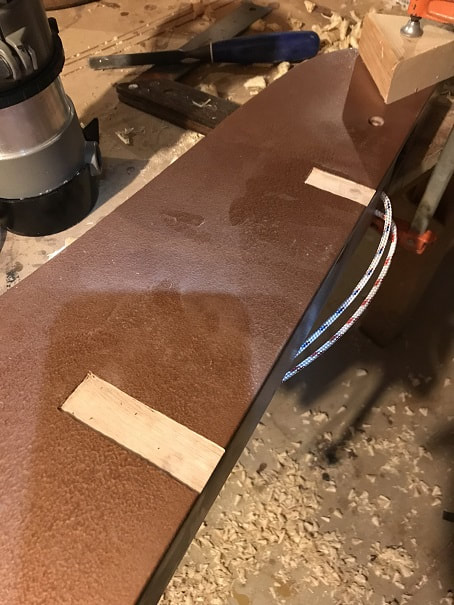
- Coated both inner centerboard faces with thickened epoxy and then clamped them together. Be sure to block up the centerboard in the middle, under the weight (tiles in my case), so that the weight in the middle does not create a bowed shape in your centerboard.
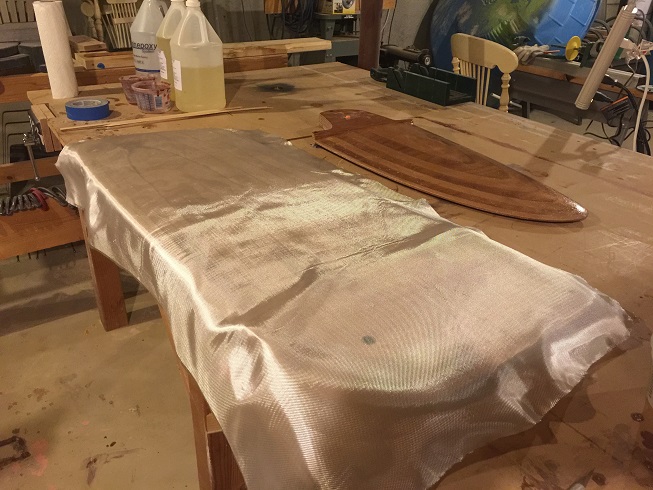
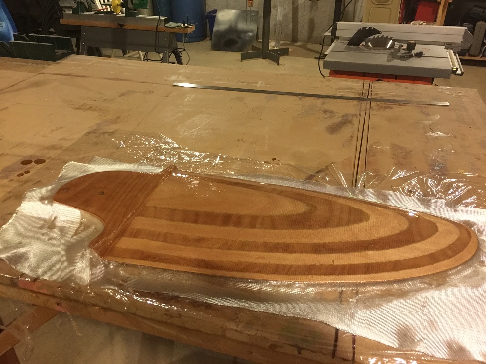
Pre-cut Fiberglass over one side of centerboard
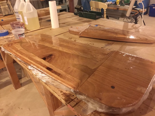
Here, I am in the process of wetting out the fiberglass over the centerboard. There are stil some thin airpockets to press out and some more epoxy needed, and I will eventually apply two layers of fiberglass over the whole centerboard plus a third layer over the leading edge.
- I am now applying 2 layers of fiberglass to the "end grain" on the bottom of the center board, and wrapping that up the sides a bit, and one layer of fiberglass on the end-grain of the top/front/back flats of the centerboard
The center board is finished with fast set epoxy thickened with graphite. I added epoxy such that it was like thick paint, but still brush-able. Very cool stuff.
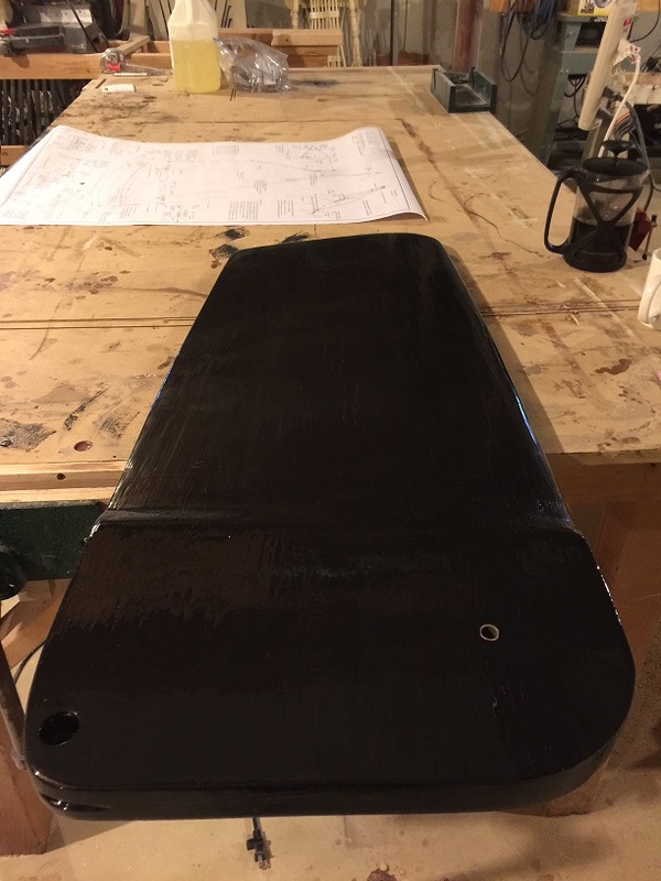
Completed SCAMP Centerboard, with bushings installed. The O.D. of the bushings were roughed-up with coarse sandpaper, then epoxied into the centerboard, then trimmed and sanded flush with the surface of the centerboard. Then a final coat of graphite epoxy.
|
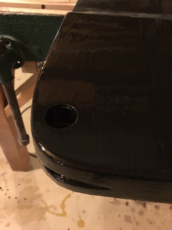
1" hole drilled down far enough to expose the uphaul line hole in the centerboard. The 1" stopper-knot-hole does not go all the way through the centerboard. Guide groove is rasped in to the top of the centerboard also.
|
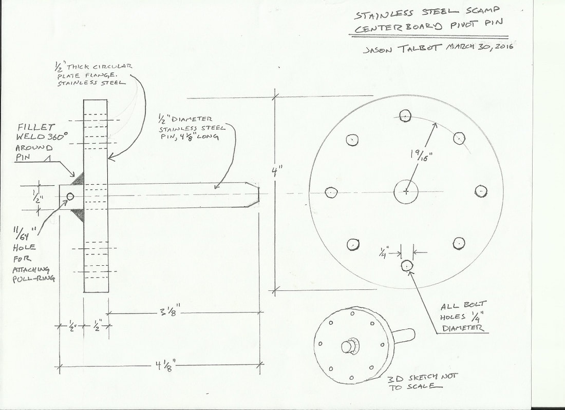
SCAMP Centerboard Pivot Pin
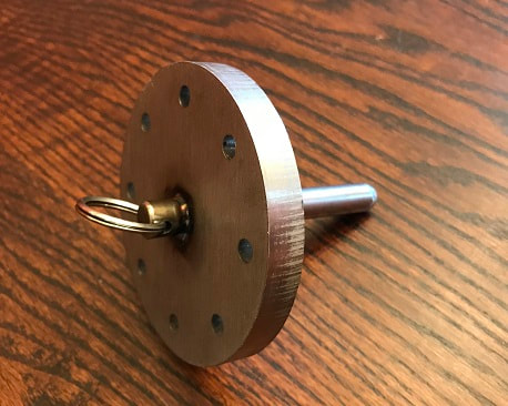
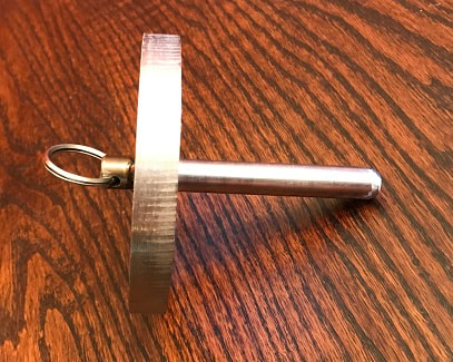
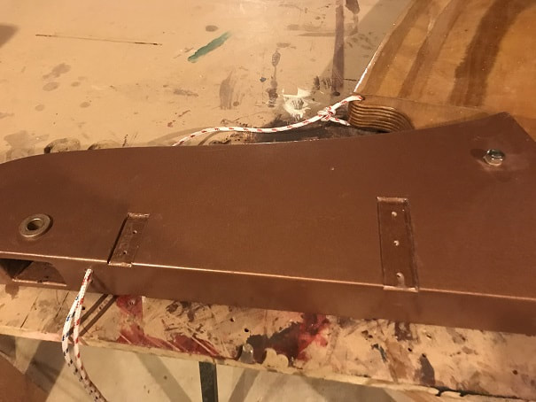
I wanted a strong centerboard pivot pin that would give me peace-of-mind regarding retention of the centerboard and elimination of risk of the pin backing-out. To that end, I designed a fabricated stainless steel flanged centerboard pin. I had purchased a stainless centerboard bolt, and was going to go that route, which is cheaper, and I have seen some great centerboard bolt retention designs out there....that said, I went a little overboard and went for the stainless fabricated centerboard pivot pin below. It will be retained using 1/4" stainless steel hex head lag screws. Based on feedback from Simeon, I updated the design to feature a more tapered end on the pin, and added a hole in the stub end, where a pulling ring can be anchored, in order to make pulling the pin out easier.
SCAMP Centerboard Pivot Pin
SCAMP Centerboard Pivot Pin
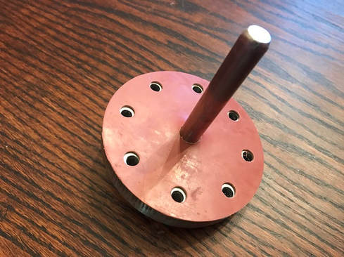
Centerboard pivot pin with gasket. I made the gasket from sheet rubber, holes made with punch.
Later in the project, with the boat flipped upright, I installed the centerboard.
- Make sure the centerboard is supported from below so that it does not just fall through the centerboard case.
- In my case, the boat is on the trailer, and the trailer bunk is directly beneath the centerboard case.
- I dropped in the centerboard, careful not to pinch my fingers.
- I held a screwdriver (in my left hand) in the centerboard-pin-hole and shuffled the centerboard around with my right hand until the hole was found, then I held it tight with my right hand and pushed in the centerboard pin. This took a couple tries.
- The pin was then tightened down and I am very happy with the result.
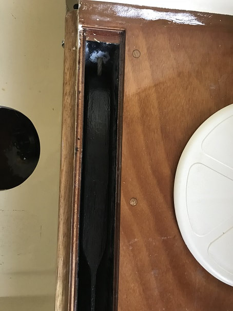
Its tough to see, but here is the centerboard in the centerboard case. I have 3/16" space total, bit under an 1/8" on each side, good to go per manual.
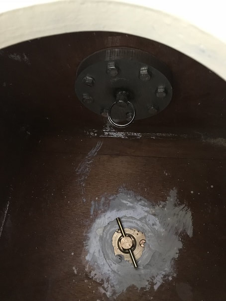
Centerboard and centerboard pivot pin installed. The bronze drainplug is the drain/fill plug for the water ballast compartment.
That's all for now on the centerboard. For detail on the hardware used for centerboard tackle, visit the hardware page
For information on the final rigging of the centerboard uphaul, please visit the SCAMP Sailboat ARGO Rigging Page
SCAMP Tiller:
- Over the years my father has gathered up a reliable inventory of neat roughsawn hardwood boards, and looking through it with him today, we found an absolutely perfect tiger-patterned straight , tight-grained piece of hickory. This will be my tiller.
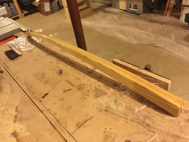
- There are some very detailed, well-dimensioned drawings online of tillers for SCAMP. That said, rightly or wrongly, I just unscientifically drew out by hand, my tiller on this piece of 1.375" thick by 43" long by 4" wide hickory that I found. I drew it with a curvature and taper that I thought looked good. Then I rough-cut the tiller on the bandsaw to create the blank below. I am excited about how it will look when carved, sanded and finished. I plan to finish it with 3 coats of epoxy and 3 coats of spar varnish.
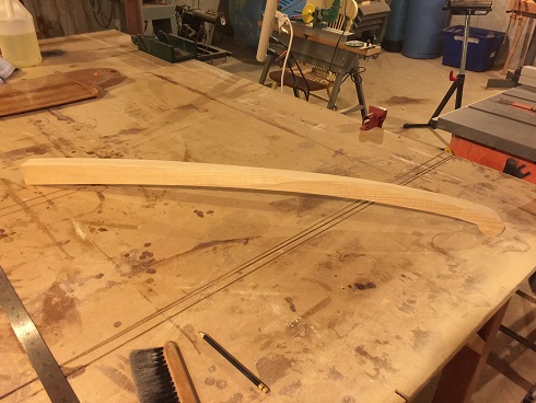
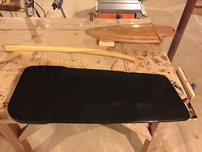
Tiller rough cut out on bandsaw
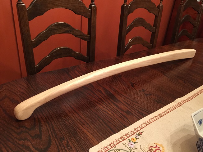
Tiller carved, filed, sanded, and ready for 3 coats epoxy + 3 coats varnish
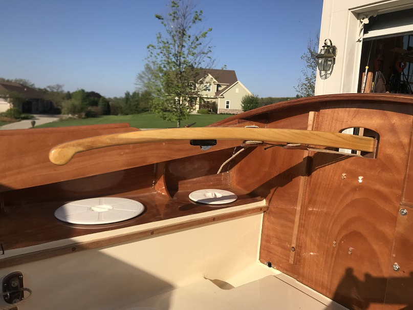
Finished tiller. I will drill and seal the hole for the retention pin when I finish the rudder stock.
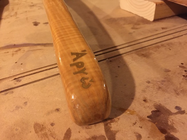
Detail of tiller handle. In gold paint, I painted "Argo" in greek on top of the 1st coat of epoxy....so the painted letters have 2 coats of epoxy and 3 coats of varnish over them.
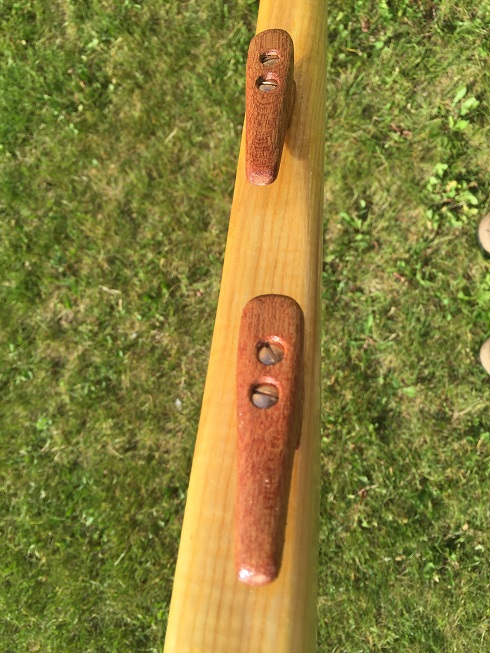
Homemade mahogany jam cleats on the bottom of the tiller. One is as far to port and one as far to starboard as possible to try to provide clear paths for the uphaul and downhaul lines to these cleats. Mounted with silicon bronze wood screws
SCAMP Rudder:
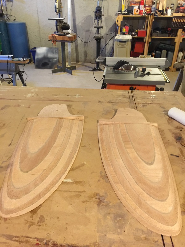
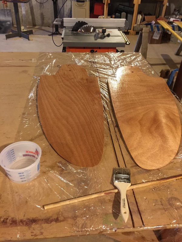
- As with the centerboard, the rudder materials were purchased from Small Craft Advisor. They send a rudder in two halves, that is already rough shaped to the correct foil cross section. The two halves must be glued together with epoxy, and covered with fiberglass.
- Mixed 6oz of slow set epoxy
- coated the surfaces to be glued together with thin coat of unthickened epoxy
- thickened the remaining epoxy with Colloidial Silicone
- Applied thickened epoxy to the surfaces to be joined
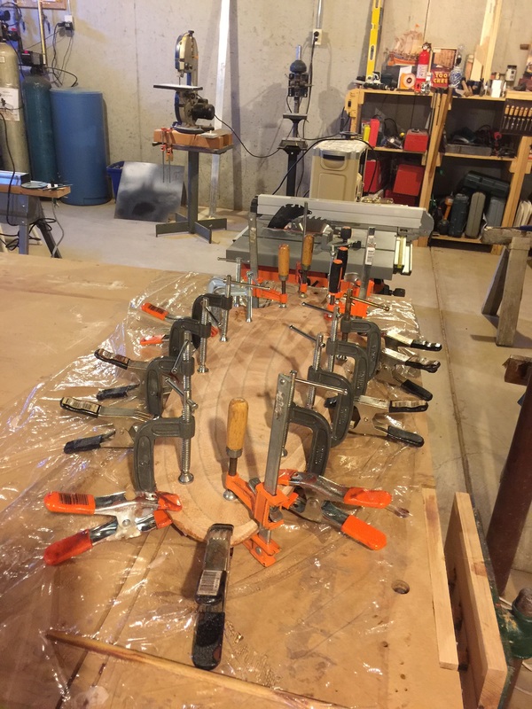
- clamped together with medium pressure and made sure the two halves were aligned to each other
- I had too much epoxy to chip off of my bench-top after gluing up the centerboard, so I wised up this time and put down Saran wrap under the rudder during glue-up.
|
|
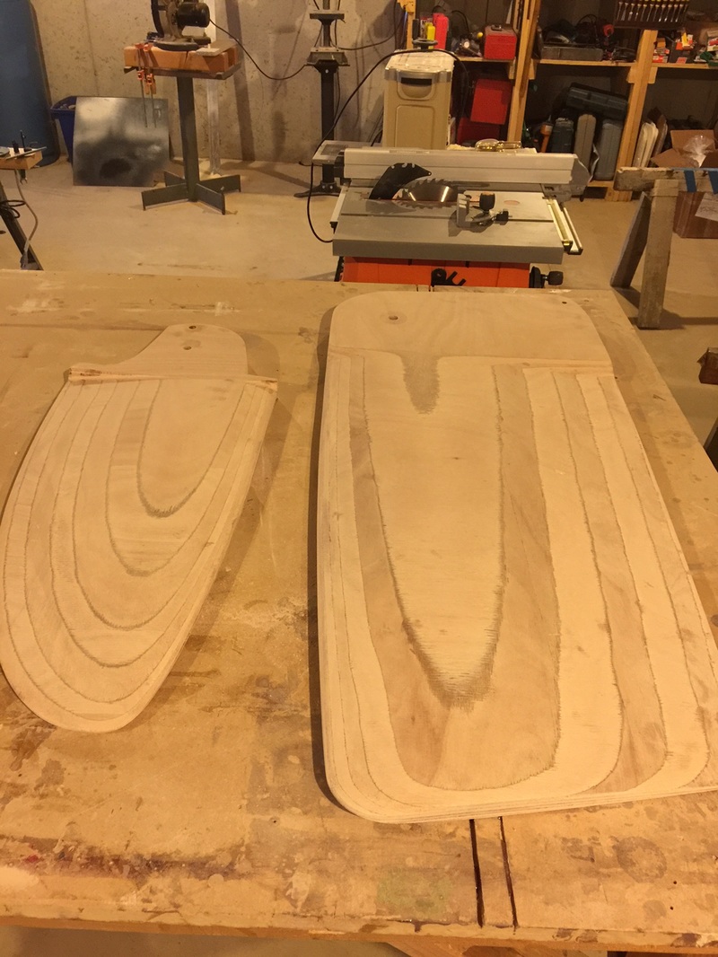
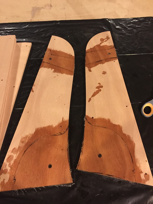
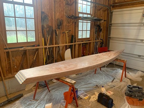
- Centerboard and Rudder glued together and sanded:
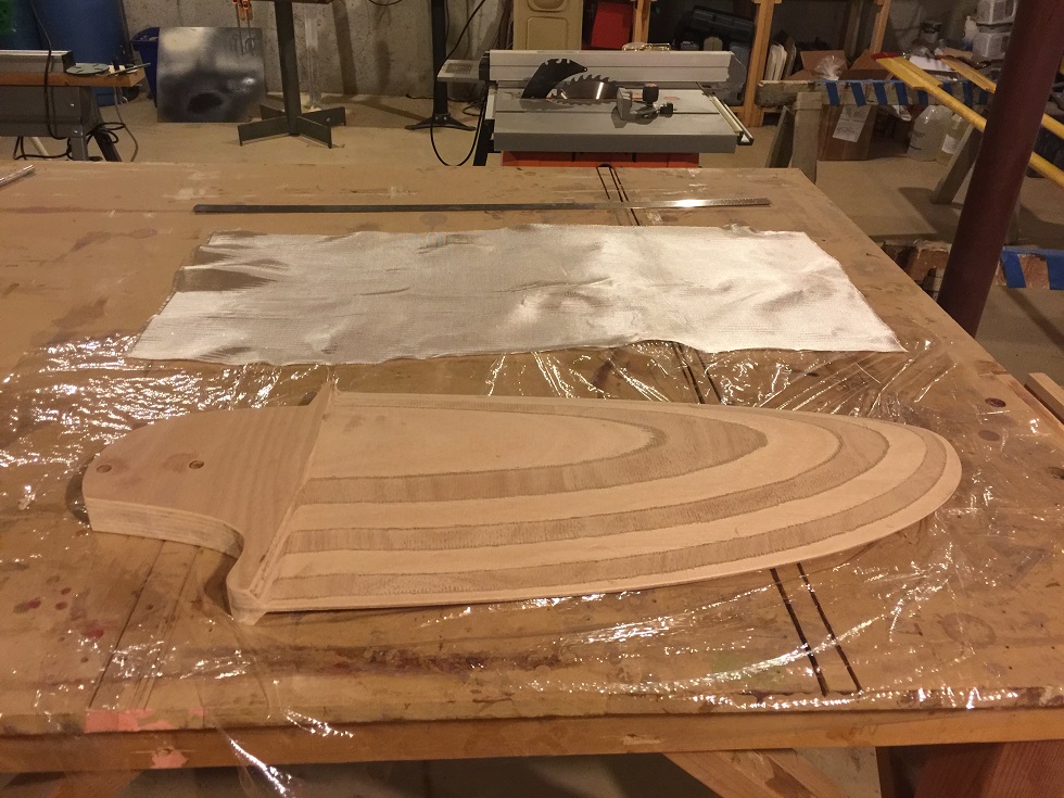
- Fiberglassing the rudder. Cut a 36" x 16" piece of fiberglass. Mixed 6oz of slow set epoxy. Cut a slit where the sharp edge is located at the transition from the top of the rudder to the foiled section, did this to allow the fiberglass to break over this edge without "bubbling" up. Coated surface of one side of the rudder with epoxy. Layed down the fiberglass and coated the fiberglass with remaining epoxy.
- Trimmed the excess fiberglass with a razor knife and sanded it smooth. Flipped the rudder over, sanded off the epoxy that had dripped onto the other side (so that I would have a fresh clean wood surface to fiberglass-to). Applied fiberglass to the other side.
- Trimmed fiberglass
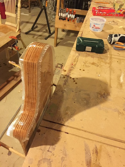
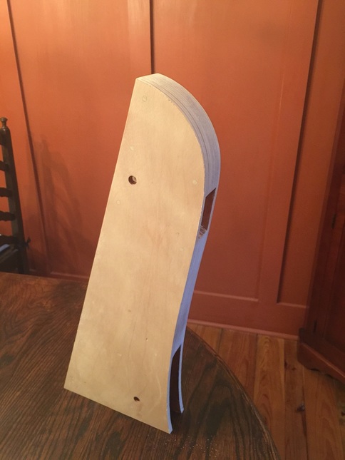
- Cut a strip to cover the "end-grain" at the top of the rudder, and held rudder in a vertical position
- fiberglassed top of rudder
- Gave the rudder a sanding and clamped it in a horizontal position, leading edge pointing up
- Applied an 8" wide strip of fiberglass on the leading edge of the rudder, carried over each side 4". filled the fiberglass and also gave the whole rudder a coat of epoxy
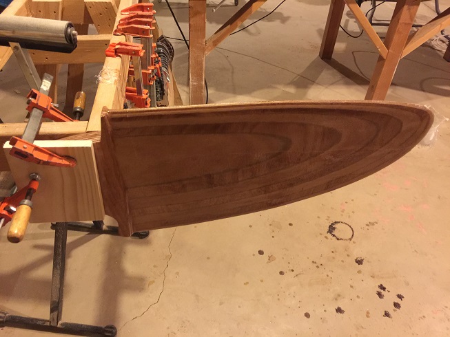
- I was concerned with durability of just one layer of fiberglass on the rudder, so I went for a final complete coverage of fiberglass. This will result in two layers of fiberglass on the whole rudder and 3 layers on the leading edge. Third layer being applied below.
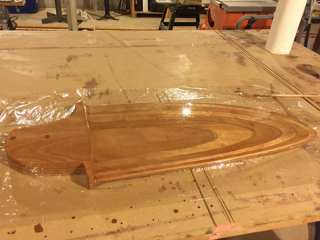
- Sanded rudder
- 2 more epoxy coats in progress:
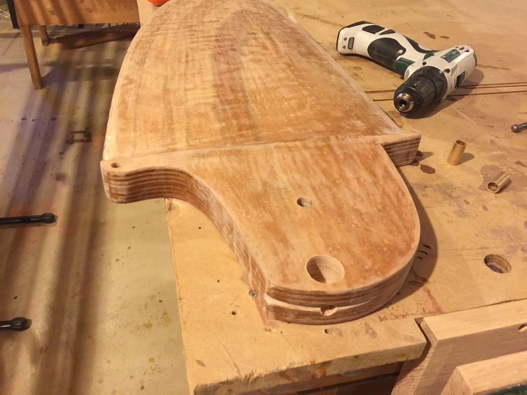
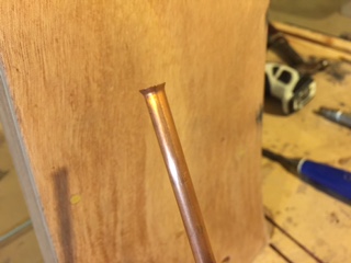
Above photo: 3/8" hole drilled for rudder uphaul: this will be filled with epoxy and drilled to 1/4" to accept the 1/4" rudder uphaul line. 1/2" hole drilled for rudder pivot (will have bushings installed in it), and 1" diameter hole drilled to provide access to rudder-downhaul. A 3/8" hole is drilled into the end of the rudder: this hole will be filled with epoxy and a 1/4" hole will be drilled through the epoxy for the rudder downhaul line. Downhaul line alignment groove has been cut into the top of the rudder with a file.
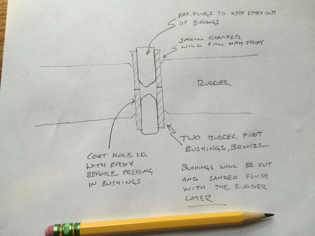
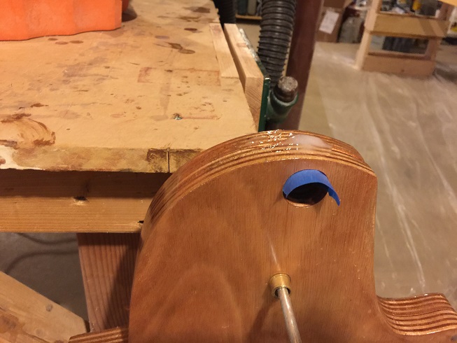
Above: Installing rudder pivot bushings.
Filling the rudder down haul hole in the top of the rudder with epoxy. After it cures I will drill a 1/4" hole through the epoxy.
- Then applied three coats of Epifanes Gloss Spar Varnish
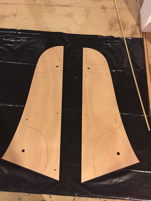
Starting construction of the SCAMP rudder Head Stock. I purchased the SCAMP kit from SCA, which included these parts. The internal blocking is made from glued up sheets of plywood and the outer stock plates are plywood also. Here I have traced out the areas where the tiller and rudder-foil will be. There is no blocking in these areas, and I will fiberglass and graphite-epoxy them to provide abrasion resistance to the motion of the rudder foil and tiller.
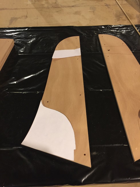
Made paper templates of the areas to be fiberglassed. I will use these to precut fiberglass for these areas.
One layer of fiberglass applied
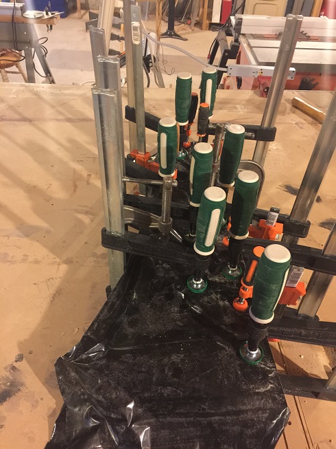
Rudder head-stock being clamped and glued together. 3/16" hardwood dowels are installed in the predrilled alignment holes, and all the plywood layers are glued together with silica-thickened-epoxy
Sanded. Now I will put two coats of graphite epoxy on the internal faces, and 2 coats of epoxy on the outer faces.
- Next, I drilled two 1/4" holes for the copper rudder uphaul/downhaul tubes. The 1/4" holes were too small and tight to fit the 1/4" copper tube through, so I drilled them to 5/16" diameter.
- Flared one end of each copper tube, filled the holes with epoxy and then pushed the tubes up through the liquid epoxy so that they were completely encased in epoxy. I filled the ends of the tubes with modeling clay to keep epoxy out.
- After the epoxy mostly hardened but was still malleable, I cut and flared the other end of the tubes. I flared by pounding the tube-ends with a conical piece of steel, worked well.
Flared-end of 1/4" copper rudder downhaul tube
|
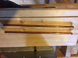
SCAMP rudder uphaul and downhaul copper tubes with one end flared
|
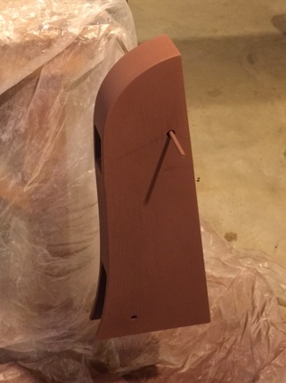
Rudder Stock after epoxy coats and rustoleum primer
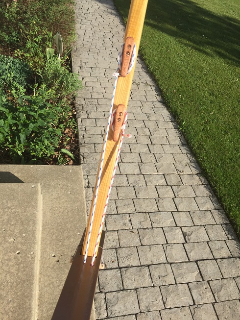
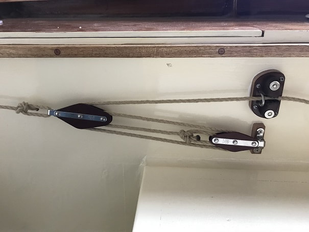
Jam cleats installed on underside of tiller. Uphaul line length was cut such that when extended 2 wraps around the jam will leave a short tail, and then retracted 3 wraps will leave a short tail. In the photo the red line (uphaul) has two wraps, and the blue (downhaul) has three. If I raise the rudder the red line would be reset with three wraps and the blue with two; and there would not be long tails after the cleats. The first really holds the line enough, and subsequent wraps are to keep lines tidy.
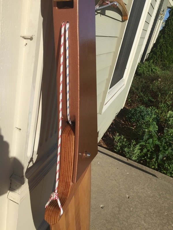
A bowline makes the uphaul fast to the tiller. The hole in the tiller was drilled oversize, filled with epoxy, and then drilled to final size. The downhaul line enters the head of the rudder through a hole similarly made, and then a figure eight stopper knot dipped in epoxy forms the stopper inside the rudder.
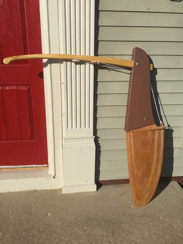
Finished SCAMP Rudder Assembly!! I used a hardwood dowel for the tiller pin. 3/16" holes are drilled through each end of the dowel, and an 1/8" dyneema line is tied between the two holes, across the top of the tiller, for retention of the pin.
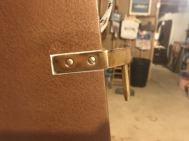
Note the auto-release camcleat added to the bottom of the tiller. In shallow water, I will be able to use this in lieu of the jam cleat, for the rudder downhaul. In the event of the rudder hitting bottom the auto-release cleat will allow the rudder to pop up. I also switched the lines to Hempex, which will be used throughout the rigging (other than the anchor rope....because hempex floats)
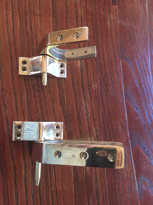
These Davey&Co bronze pintles and gudgeons will be used to hang the rudder on the boat; I will wait until the hull is finished to locate and mount the pintles and gudgeons on the rudder and stern.
The opening width of the pintles above is 2-1/16"......and my rudder headstock wound up at 2-1/4" thick. So I traced out the location and perimeter of the pintles and routed a recess so that they could be mounted.
These recesses are routed in evenly on both sides of the headstock; now I will paint them.
Recesses for pintles predrilled and painted.
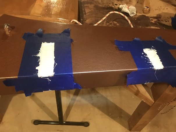
I wanted nice clean bedding compound lines, so I taped off the recessed and then laid down 3M4200.
Secured with silicon bronze screws and tape removed.
I realized that I hadn't installed bushings in the tiller pin hole in the rudder headstock, so I did that today. I scored the bushing O.D.s with a file and epoxied them in place.
Detail on mounting the gudgeons to the transom may be found on the Mounting Hardware Page