March 2022
I think German Cuckoo Clocks are fascinating works of mechanical and artistic wonder! I had been contemplating buying one, but they are quite expensive and I found myself without a project at the time, so decided to build a cuckoo clock. There are many books on clock repair, but I did not find a good resource on new clock design. Note that when I write "clock design" I mean the housing and the installation of the mechanism and pieces and linkages.....not the design of the clock movement itself. It is a challenge to know how the pieces and linkages work, so I just dove in an bought parts that I estimated would work well together. I think the best way for me to figure out how these mechanisms work is to get my hands on one!
Here is the build-log of building my Cuckoo Clock.
I decided to build it as a "Grandfather" clock in a tall case standing on the floor; Building a traditional wall-mounted cuckoo clock would be the same, but the weights would just fall down through the open air rather than into the standing tall clock case.
I will update the log below as I make progress (or mistakes).
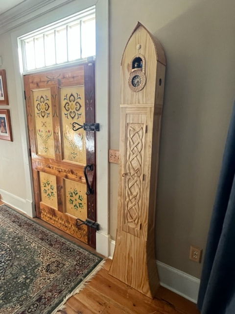
Handmade Grandfather Cuckoo Clock
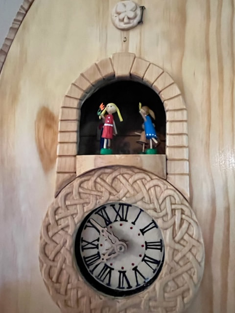
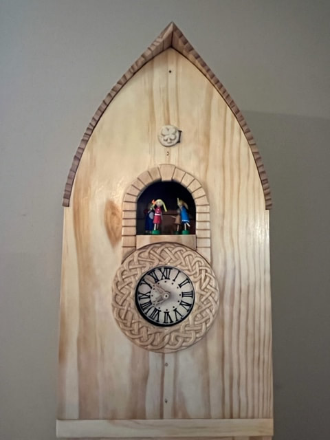
Here is a close up of the face of the finished clock, dancers, and cuckoo-bird door.
First; here are the components I bought (many online stores are available for Cuckoo Clock parts)
Movement:
Regula is the largest manufacturer of cuckoo clock movements, I believe. These are made in Germany. I selected an 8 day (meaning it should run for a week) movement that also powers a music box (not part of the clock movement) and also a dancers table which is integral and attached to the clock movement. This will be a fully mechanical clock with no electricity, and will be powered by three 1750gram weights on chains.
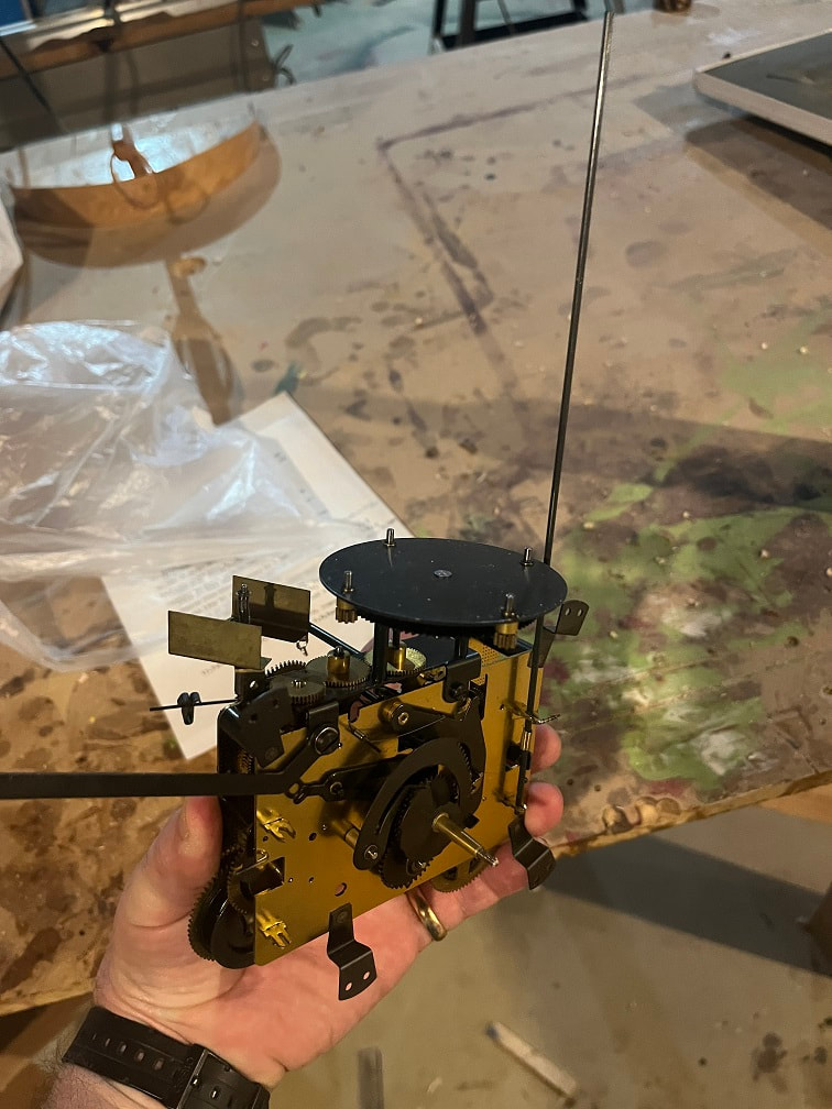
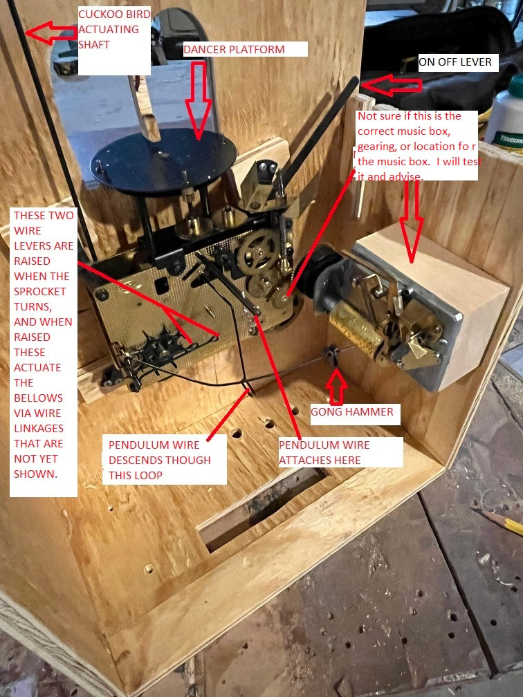
I selected a Regula 72, 8 day movement, with a dancing table and gears to drive a music box. This mechanism therefore will be driven by 3 weights, and has three main wheels. This is a view of the front of the mechanism, with the mainshaft that drives the hour and minute hands protruding from the front center. The round black table on the top is the dancers platform. The tall vertical rod is what opens the cuckoo door, and the lever on the left is the on-off lever.
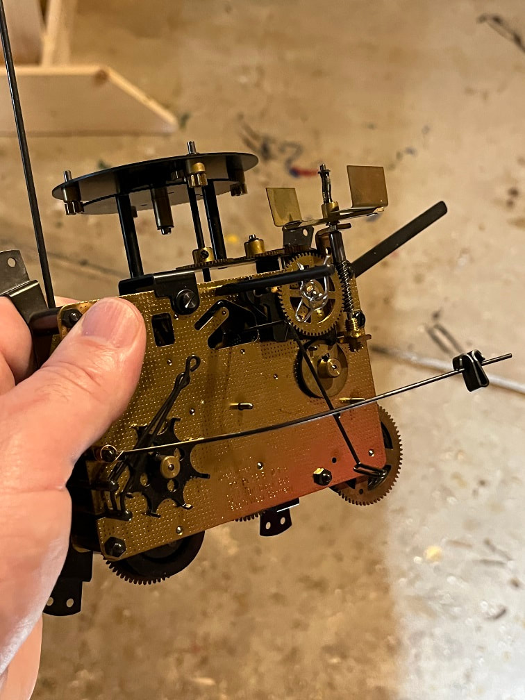
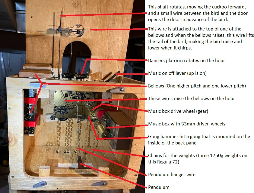
View of the back of the Regula 72 , 8-day, clock/musicbox/dancer platform movement.
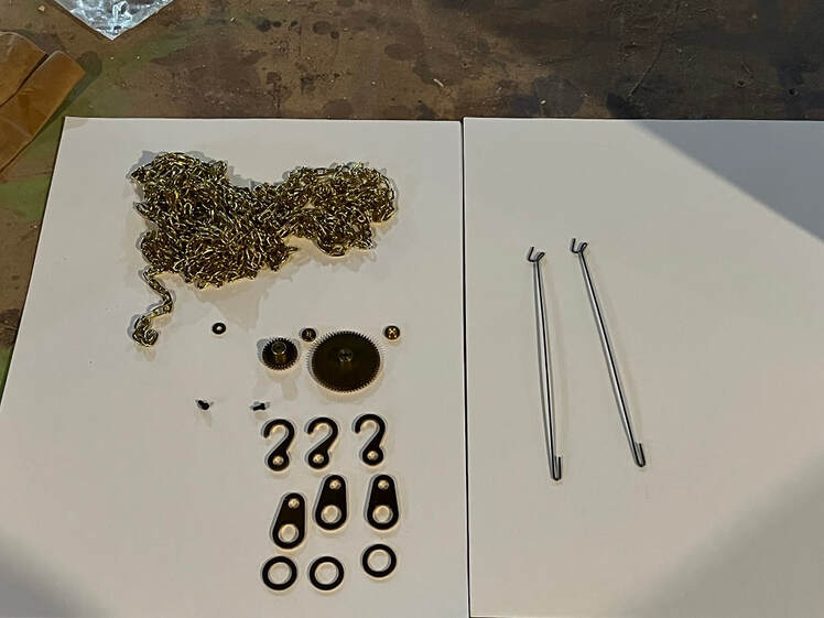
The Regula 72 came with chains for the weights and hooks/rings for the ends of the chains. It also came with extra gears that I'm not sure what are for. I bought the two wire linkages on the right to lift the bellows, I'm not sure yet, if they are the right length.
Bellows:
Two old-fashioned bellows and pipes make the high and low "Coo" "Coo" sound that is so familiar to cuckoo clocks. There are manual linkages that lift up the bellows, filling them with air, and then the bellows compress and send air through the pipe to make the sound. I selected 5 1/2" bellows with the pipe opening on the back of them.
Here the bellows are open, just letting the bellows fall shut makes the coo noise.
Here you can see the bottom of the bellows, the one on the right has a longer pipe length and will make a lower pitch than the shorter pipe-length on the right.
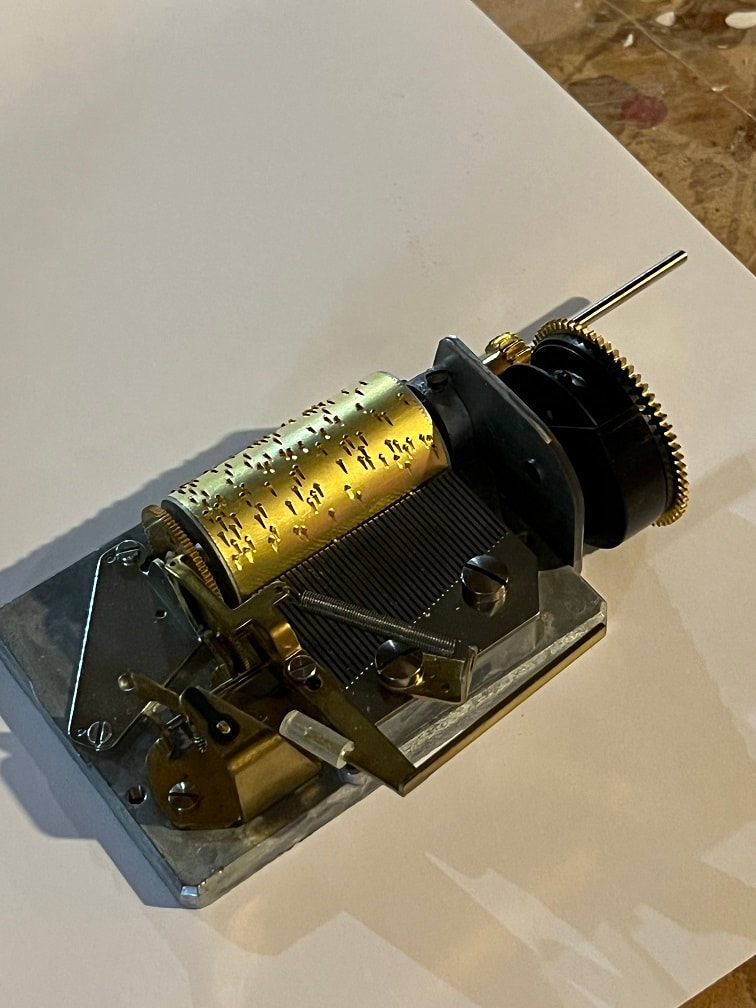
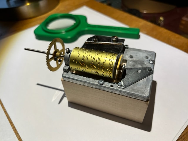
Music Box
I found a 36 tooth music box that plays Edelweiss and German Wanderer. I see that the music box I bought has a wheel/sprocket that I could hang a weight on to drive the music box, and it also has a shut-off mechanism, but I think both those features are already built into the Regula 72 movement, so I will need to find a way to make this music box work with the mechanism. I will also need to verify that the resulting rpm of the music box drum is correct, if not I may need to find some different diameter gears. During testing I learned this is the wrong music box to use with a Regula 72! I needed to make significant modifications to get it to work. DO NOT spin the music box drum in the wrong direction as this will damage it. The pins on the drum should rotate up from below the tines, lifting a tine to make a sound.
Some clock terms I have learned (that I will probably fail to use consistently) are: Gears are called wheels, shafts are called arbors, bearing points are called pivots, and the linkages are called wires and levers.
So, those are the initial components that I bought. Now onto learning about these mechanisms, and building the cuckoo clock case.
First I will build a trial clock case and stand, then once I understand the design and dimensions, I will share those on this page and build the final clock case!
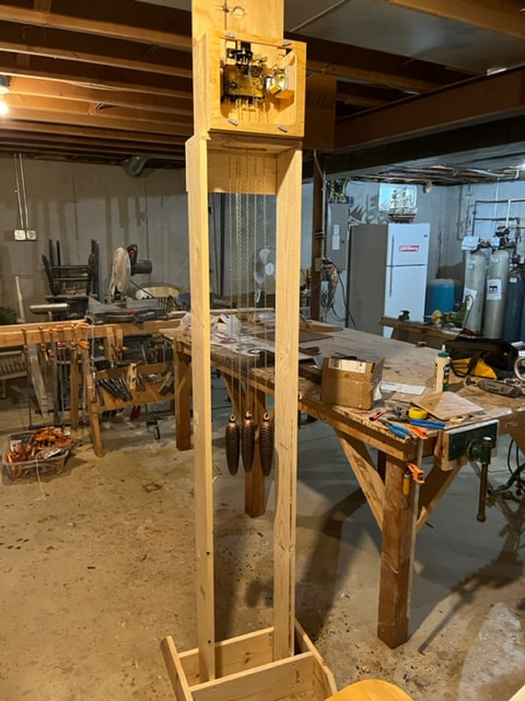
I decided to build a mock-up of the clock using cheap lumber so that I can learn the dimensions and fit of all the parts, then I will build the finished clock once I know how these things work! The 8 day movements have weights and chains that need about 6 feet of drop, so that's how tall I built the test stand.
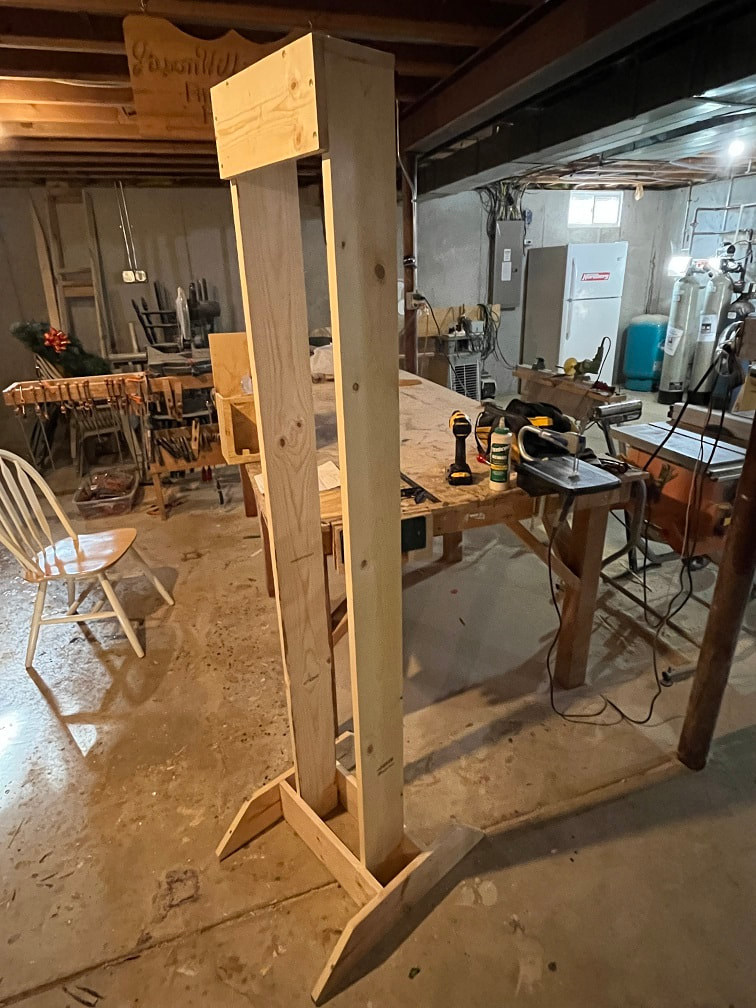
6ft tall test stand for cuckoo clock mechanism.
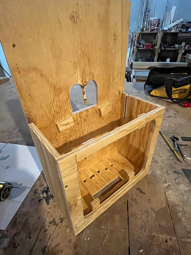
I measured up the Regula 72 as well as I could and build this case for it. There is a slot for the on/off lever, a window/doors for the dancers, a hole for the clock shaft, and holes in the bottom for the pendulum and weight chains. It seemed that the movement needed to be set back from the front a bit, so I added 3/8" mounting blocks which you can see glued to the inside front of the case. The back has a removable service panel.
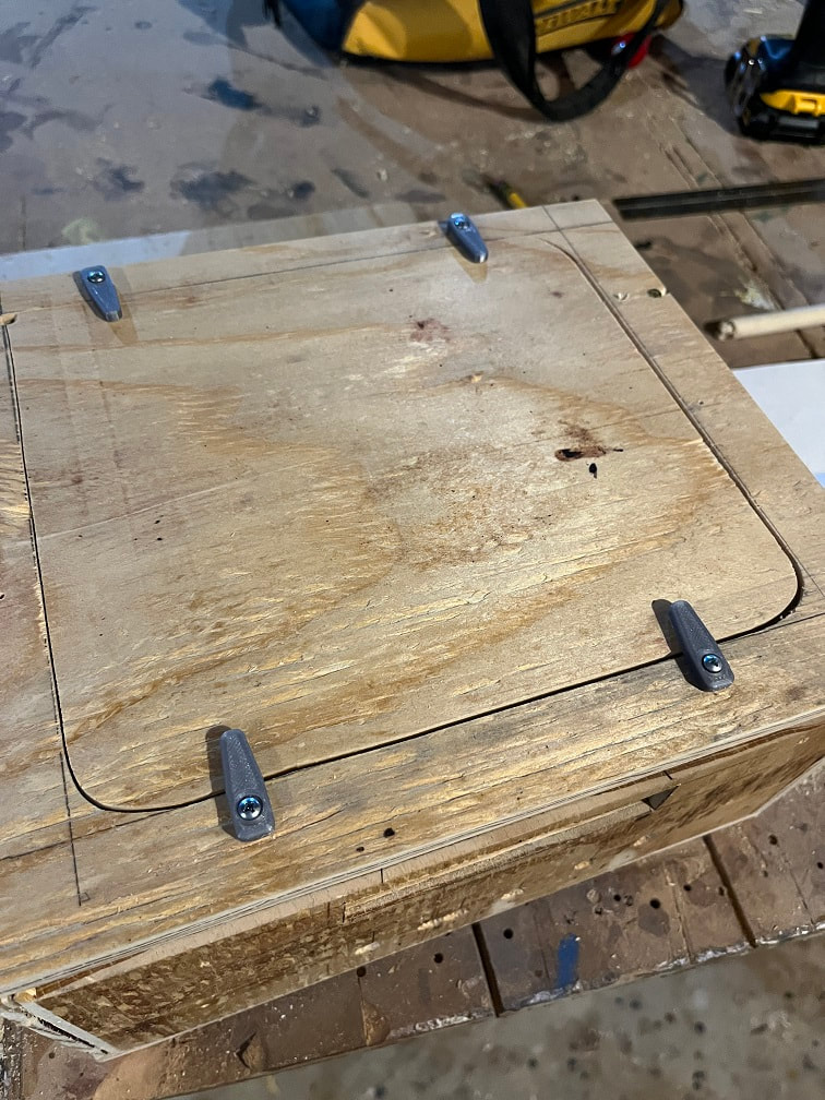
Closure latches hold the back panel in place.
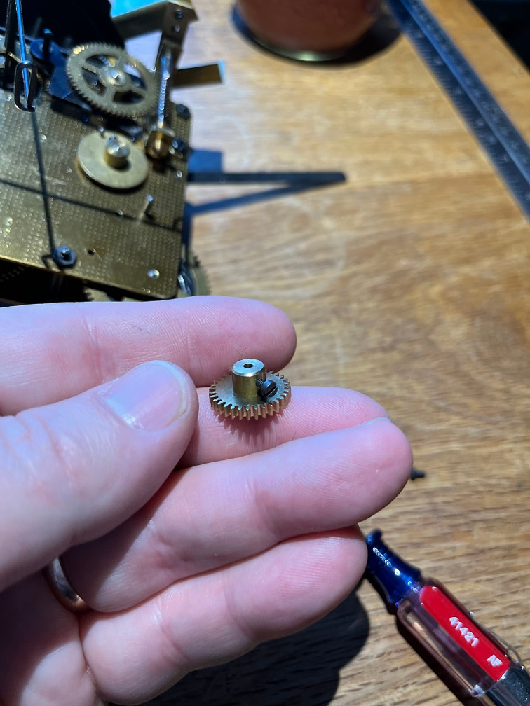
Before screwing the movement into the case I added the music-box drive gear, this is what it looks like, and it has a set-screw to secure it to the shaft.
A bit of googling led me to believe that this was the shaft to mount the music-box drive gear, so I mounted it here.
Mounted the Regula 72 into my test-case.
On/Off lever fits in the slot. Now that I know exactly where it aligns, I can make the slot smaller in the final clock frame.
Gong hammer is about 1/4" from the back of the case, which is where I wanted it. There is a metal spring called a "Gong" that this little hammer hits in order to make a gong chime noise. The Gong itself will attach the inside of the back access panel.
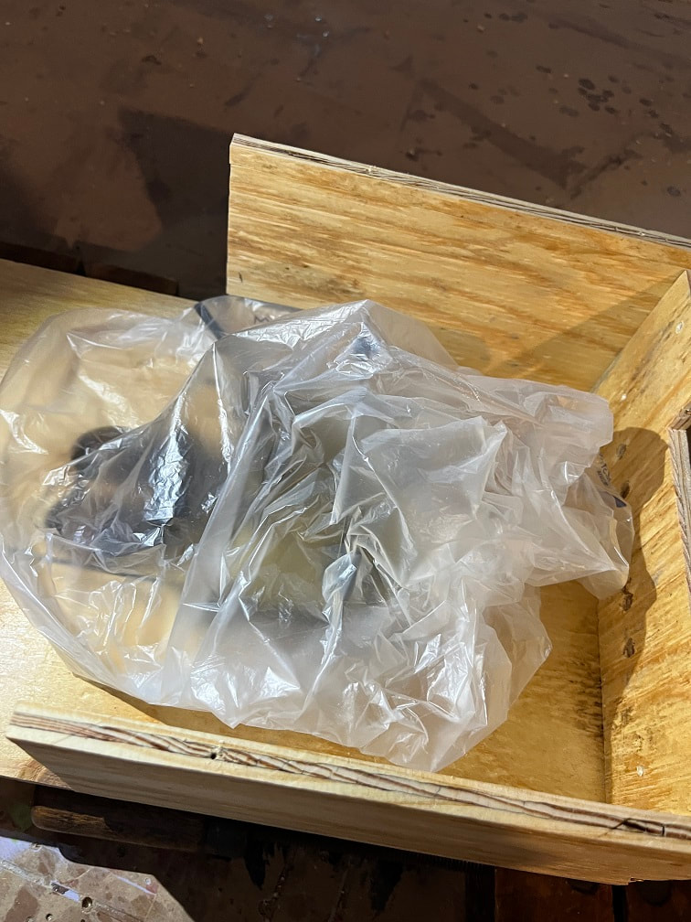
I am concerned about dust getting into the mechanisms so I continually keep the bagged or covered.
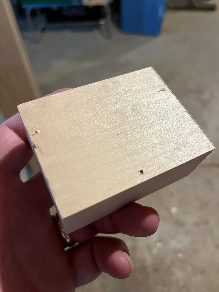
Solid basswood carving block made to my estimated dimensions to hold the music box in the correct position vs the drive gear on the movement.
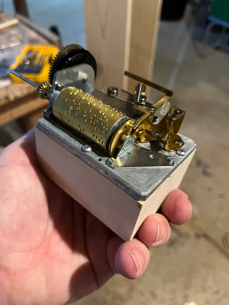
Here is the music box screwed onto the mounting block.
After adding another 1" to the depth of the case, it now holds all the pieces well. PLEASE NOTE: After I got the weights and ran the clock, I verified that the music box I bought shown in the photo needed significant modifications in order to work with the Regula 72. Those modifications can be seen below. The music box arrangement shown in this photo is not correct.
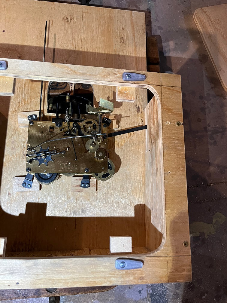
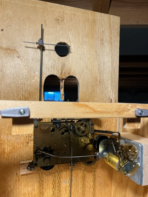
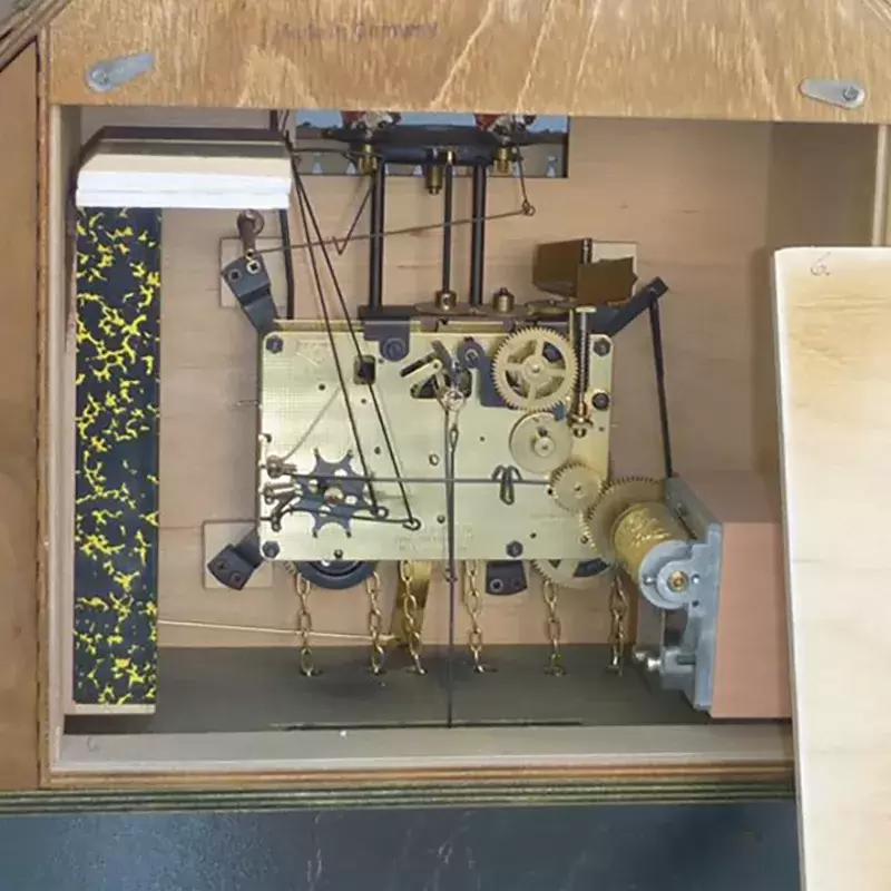
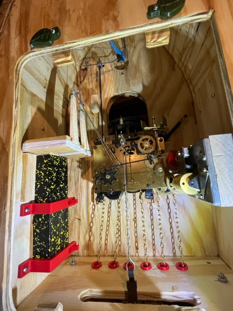
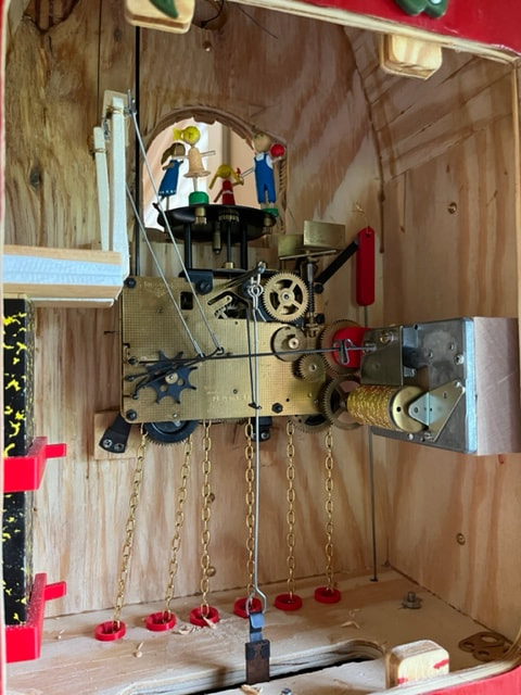
Internal layout of my Cuckoo Clock workings
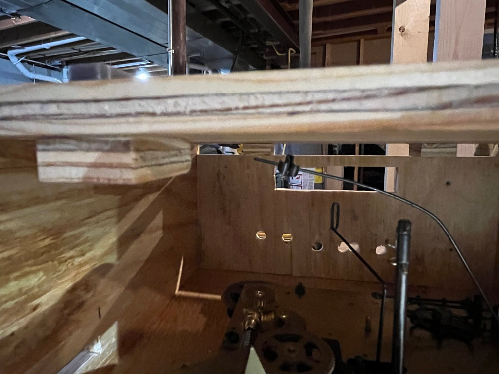
I am skipping ahead a bit here, but here is a photo of the completed test case that I built showing the final orientation of the components and also the modified music box.
Lubricating the clock movement and installing the chains
I believe the mechanism was unlubricated, so before I started running it, I removed it from the case and lubricated the front and back plate pivot points. I used Liberty 100% synthetic clock oil and carefully lubricated the pivots. From what i've read each pivot takes about the amount of oil that would fit in a small needle-eye. Extra oil will drip and draw oil out of the pivot rather than lubricating it. Also extra oil all over will only attract dust and gum up the works. I sparingly lubed up the pivot points. Then I ran the chains through the mechanism, this was a bit tricky. The wheels only rotate freely one way; find out which way that is and feed the chain in in the direction that the wheel freely rotates. I tied a very small brass thread to the end of the chain and fed that through the wheels and then mickeyed around jostling the chain until I could pull it through. Good luck, have patience.
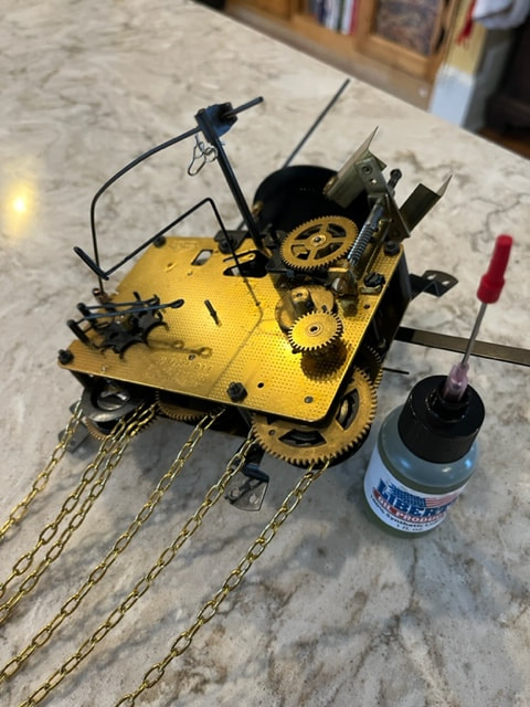
Chains installed and movement oiled.
Cuckoo clock assembly: adding the weights and pendulum:
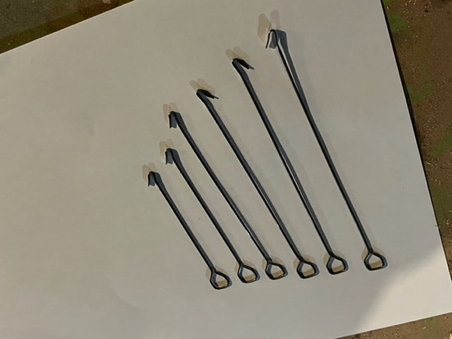
I'm not sure what length of pendulum drop hook I am supposed to use, so I will have to test this. The website I bought from said I need a 28.5cm mechanism, but I need to learn what that means. For a couple bucks I got a package of cuckoo clock pendulum wires in range from 3.5" to 6", so I can experiment with these.
Now as I wait for the weights to arrive, I will make some other little parts to keep progress moving along with the cuckoo clock project.
Plastic Guide Bushings for the chains: I designed some bushings that I will install in the bottom of the case, for the weight chains to glide through. I designed a radius into the top an bottom entries into the bushings so the chains will have a smooth ride. I 3D printed these, but one could buy nylon bushings from the store and make those work also, or you could just run the chains through holes in the wood.
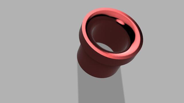
Bushing designed using Fusion 360.
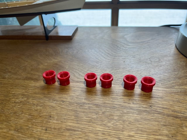
Here are the printed up chain bushings, I will install these in the final clock but not the test case.
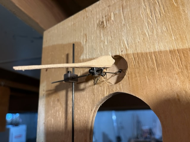
Cuckoo Actuator Shaft Joint: The Regula 72 has a vertical shaft that rotates and actuates the forward motion of the cuckoo bird (which also opens the door). The Regula 72 cuckoo actuator does not bend horizontally over to where the cuckoo door is, so I will need to find a way to firmly attach a horizontal wire to the vertical actuator shaft. Here's how I did it. I designed a union block/joint block with holes for the metal wires and also holes for set-screws. I offset the holes for the wires a bit to allow for a longer threaded hole for more purchase length of the set screws. Printed it on my 3D printer, cut in the threads and voila, done! One could also buy one of these parts.

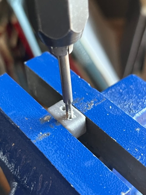
Threading the holes with #4 - 40 tap.
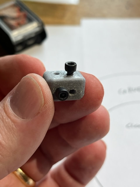
Here's the finished joint block with set screws.
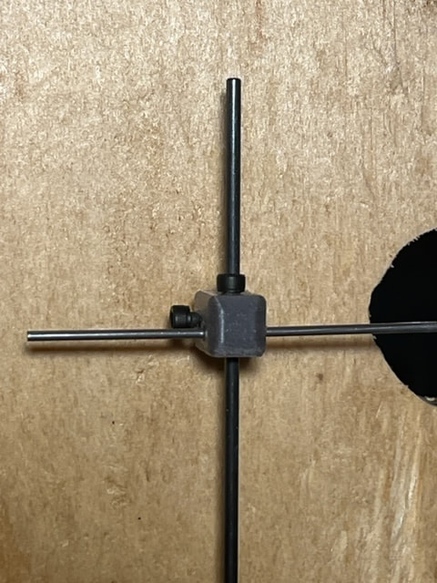
I was able to crank these little allen head set screws very tight without feeling any stripping of the threads. Very pleased.
Current view of the inside of the case.
Experimenting with the Cuckoo Door: I want a round little hobbit door for my Cuckoo (which I will paint like a Robin, the Wisconsin State Bird). I made a little round test door and hinge which I am pleased with, it opens and closes just by blowing on it.
Hard steel wire hinge: I cut and bent this hinge to shape. This is not loose flexible metal wire, it has to be bent with pliers and then rigidly holds its shape.....also if you try to bend it multiple times it will snap.
I made a little round test door and installed the hinge into the door and the scrap wood after drilling pilot holes with a pin-vise.
Attaching Weights to my Cuckoo Clock
My three 1750g weights arrived today! Very exciting , as now I can test run the mechanism as see how it works. First I checked which chain-end the weights go on (the end that doesn't move when you pull on it) and which end the stop loop goes on (this prevents the chain from getting sucked right through and out of the movement). I opened the final link in the chain with pliers and installed the hooks and loops, and then reclosed the links.
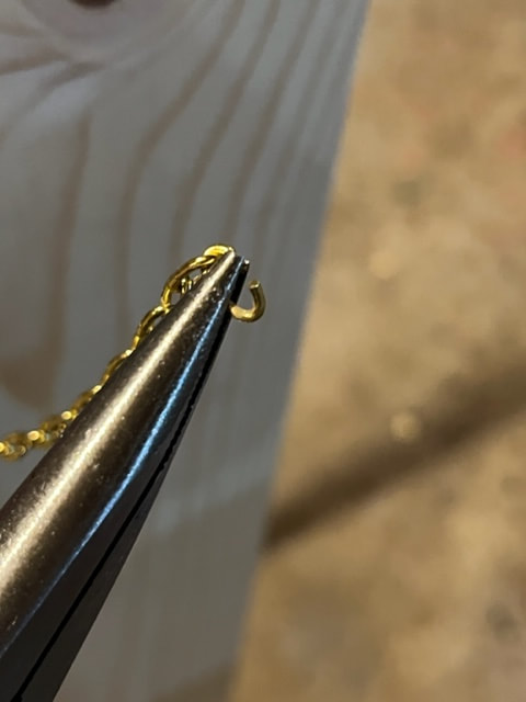
Clock weight chain link opened.
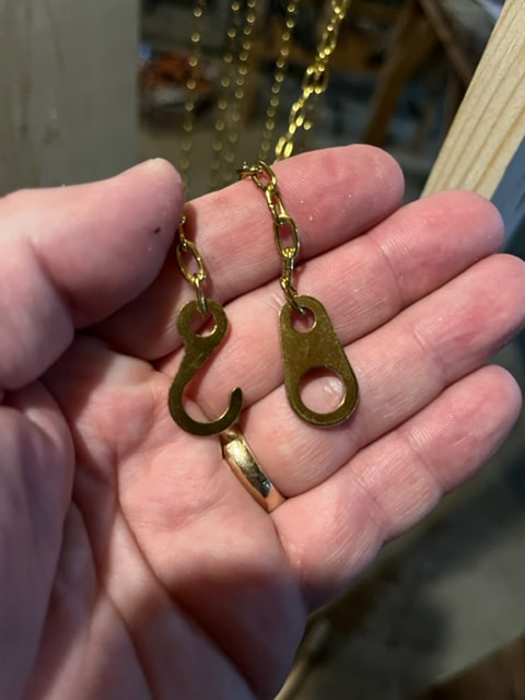
Hook and loop attached.
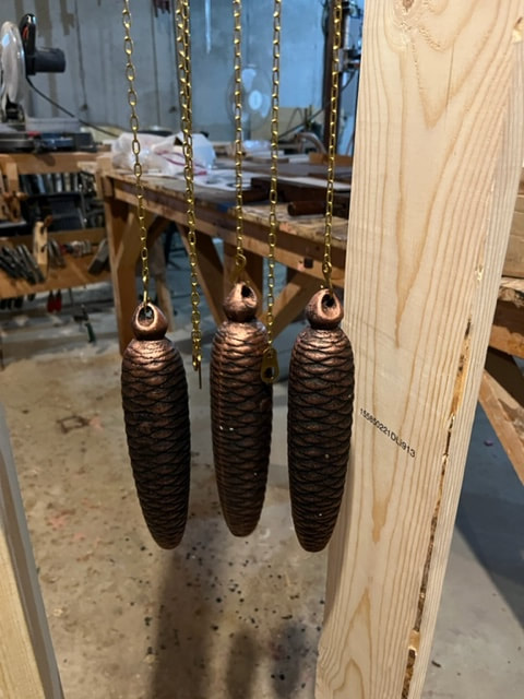
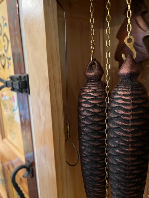
Weights hung from the hooks. I opted for three 1750g hooks which is the correct weight for the Regula 72 according to my research, though some sites said 1500g would suffice.
When I attached the weights I was very happy to see the movement start ticking away! It ticks much faster with out the pendulum attached.
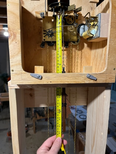
Installing the Pendulum, and checking the length: The description of my Regula 72 movement on the website said it operates with a 28.5cm pendulum. Some research lead me to understand that this is the dimension from the pendulum suspension post at the top of the movement plate - down to the center of the pendulum weight. I measured this and slid the pendulum weight so that its center was at 28.5cm.
Installing the gong to the rear plate of the cuckoo box case:
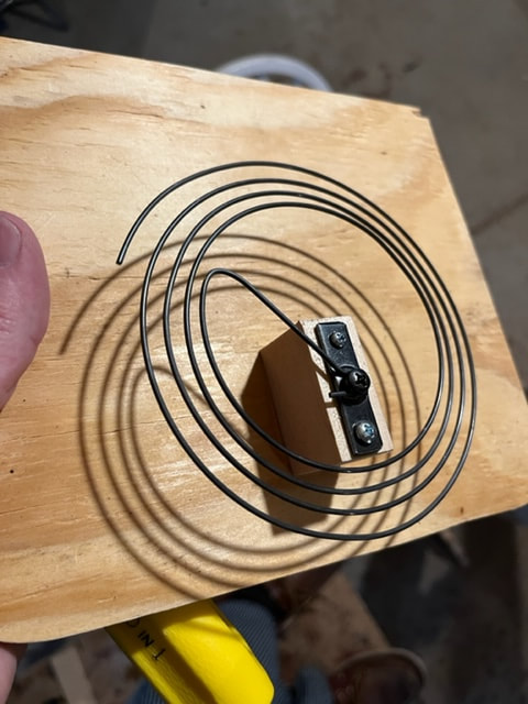
The gong needs to be installed so that it is in-line with, and just beneath the gong hammer. I measured this and built a little wooden block to locate the gong under the hammer. The mounting hook at the middle of the gong is off-center, so by loosening it a bit and rotating the gong, one can raise and lower it to fine tune it just under the gong-hammer, I did this.
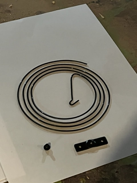
Cuckoo gong and mounting bracket. The bracket is nice because it comes with a threaded hole and screw and it holds the gong a bit proud of the mounting block.
I measured the distance into the frame the gong needed to be in order to be just below the gong-hammer and here it is installed on the inside of the rear access panel.
Here is a top view of the gong and hammer, showing their alignment.
Testing the movement and alignment of gong and music box:
Now that I have weights I can run the clock and see which way wheel spin and see how the mechanism moves! THE GONG WORKS! Happy progress!
The music box on the other hand is the incorrect one for the Regula 72. The regula 72 already has 3 chains including a weight for the music box AND the regula 72 has the start/stop mechanism built in for the music box. I already bought the one I have so I took the start/stop latch mechanism off the music box as well as the chain drive sprocket and gears.
The music box on the other hand is the incorrect one for the Regula 72. The regula 72 already has 3 chains including a weight for the music box AND the regula 72 has the start/stop mechanism built in for the music box. I already bought the one I have so I took the start/stop latch mechanism off the music box as well as the chain drive sprocket and gears.
Here is the music box stripped down to just the music drum and the comb. I bought 2 33mm wheels (gears) that will fit the shaft on the music box.
I found this photo of a Regula 72 with bellows and music box! This isn't mine but this is the setup I am shooting for, so very helpful photo.
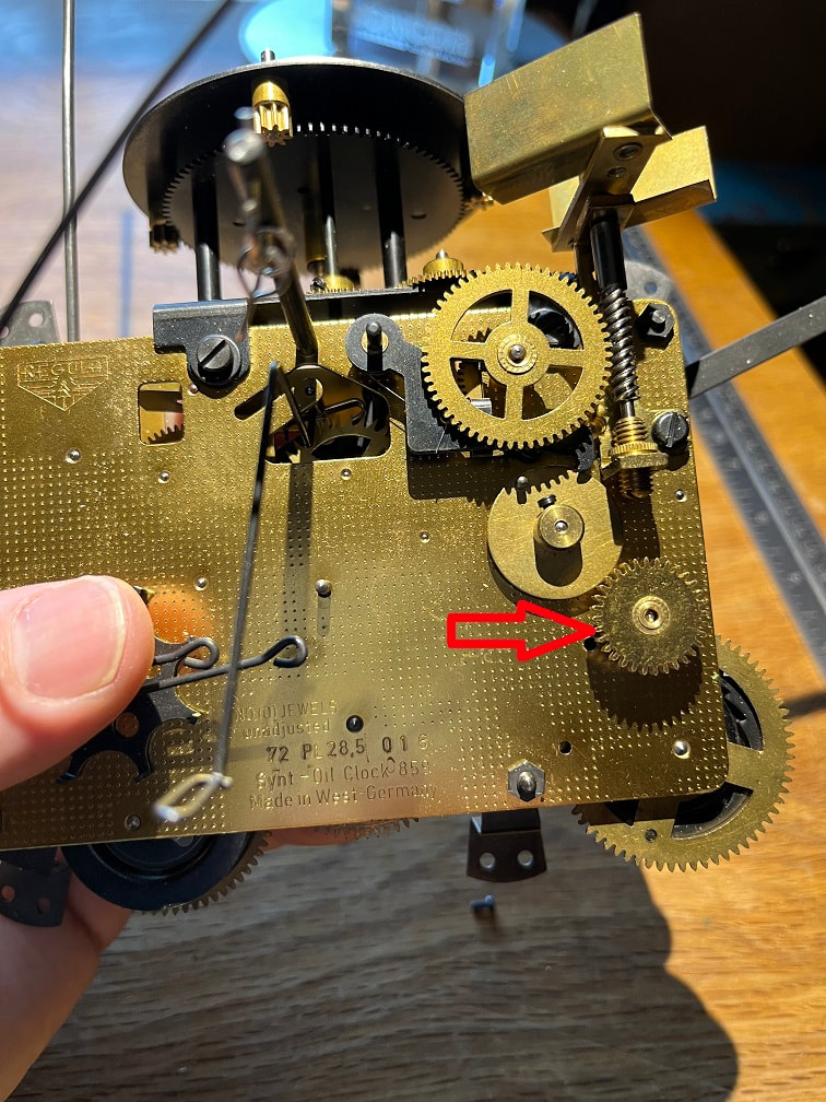
PROBLEM!: The music-box drive wheel on the Regula 72 spins counterclock wise, this will correctly drive the music box shown in the photo above, but the shaft on mine sticks out the other side, so if I mount my music box to the Regula 72 as-is, the mechanism will spin the drum of the music box in the wrong direction. I tried to see if I could loosen the shaft and just push it through the music-box drum and out the other side , but this was not possible. To overcome the wrong-direction problem, I added an additional 33mm wheel into the wheel-train which will reverse the direction of the music box wheel and also won't change the rpm of the 33mm music box wheel.
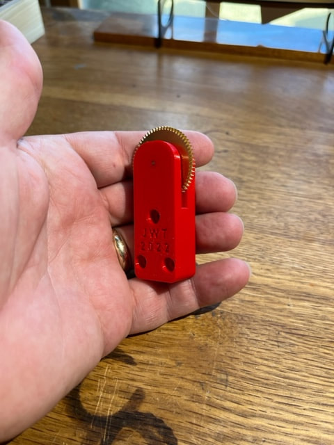
I made this little gear-holder to fit on the music box block, I also measured and designed it to fit-up with the drive gear on the regula 72 without interfering with the movement frame plates.
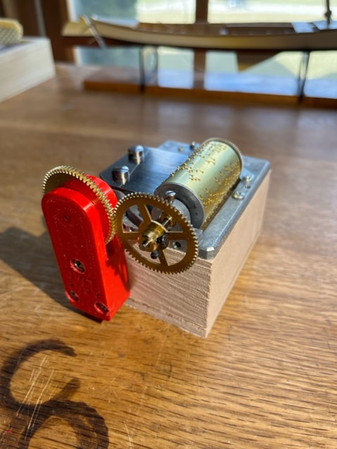
Here is the finished, modified, music box assembly. The new gear will reverse the direction and now the drum will spin in the correct direction. I also cut off the excess steel shaft length on the music box.
Installing the hour and minute hands on the cuckoo clock:
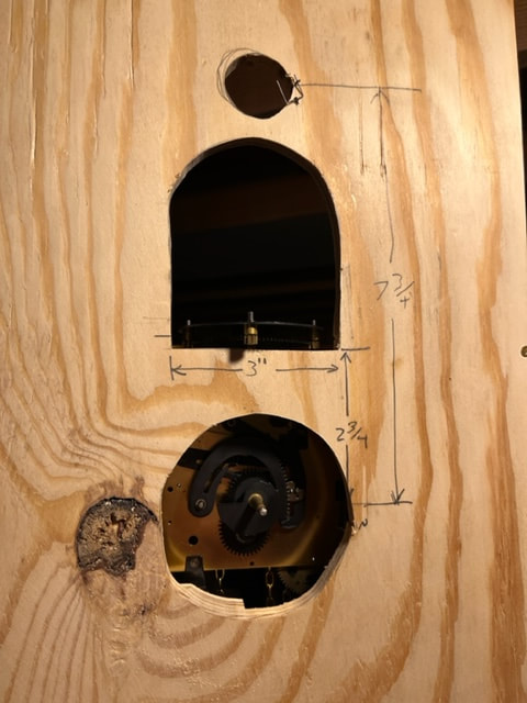
This will be very helpful as it will allow me to advance the minute hand to the hour and half hour which will engage the movements and I can see how they move. Before this, I have had to wait a half an hour or hour to then try and see the movement go through its cycle. First I realized that the shaft/arbor wasn't protruding far enough from the face of the case to be able to install the hands, so out came the whole movement, and I cut out some larger holes in the front of the case.
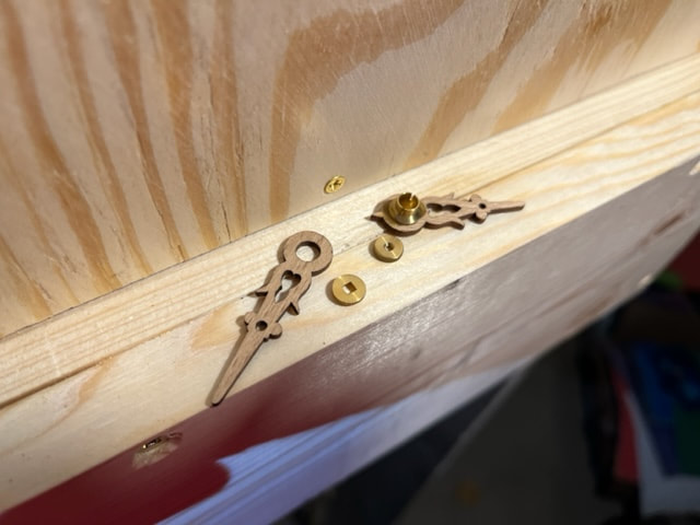
The shorter hour hand on the right, comes fitted with a brass bushing and this hand is simply pressed onto the clock hour arbor.
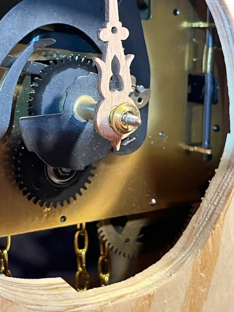
Hour hand pressed on, and then the little brass bushing with the square center can be installed next, which drives the minute hand. The raised circle lip on this brass bushing needs to face outward, as the minute hand will settle right over that raised round brass lip.
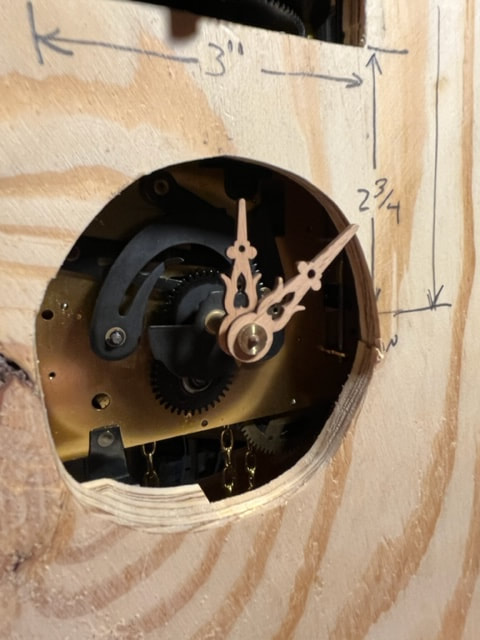
Then I put on the minute hand and tightened it in place with the small threaded brass finger nut.
Below is a photo of the installation of the music box with the additional gear to reverse the rotational direction so that the music box drum turn in the correct direction. IT works perfectly. Please note: When you install the music box into the clock, be sure to rotate the music box until a song ends and the tines are in the space between songs, this way when the movement initiates a song, the music box will start at the beginning of a song.
Installed, modified music box. I ran the movement through the hour and the music box works perfectly!!! Yeah!
Installing the bellows:
I made some small eyelets from steel wire and superglued them into the front tops of the bellows. I then designed and 3D printed two brackets that will hold the bellows to the inside of the case. These brackets will also allow me to slide the bellows up and down to locate the exact right vertical position for them.
Little eyelets, I will use two for the bellows.
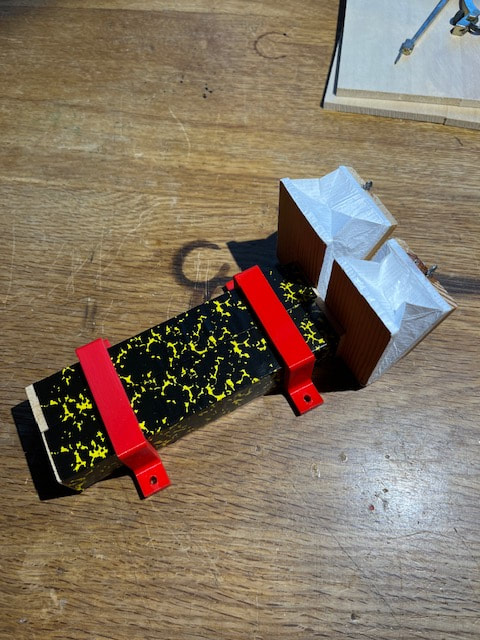
Two brackets for mounting the bellows and if you look closely you can see the little eyelets at the top of the bellows.
Version 2, improved bellows hold-down brackets:
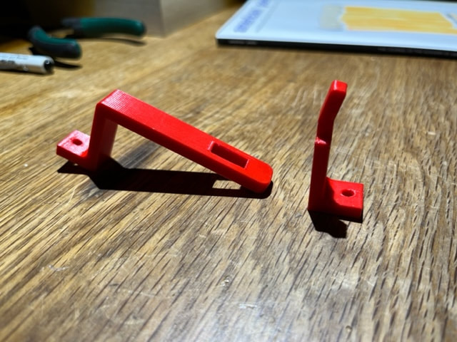
Probably as anyone who has worked on cuckoo-clocks knows, and as I just learned.....installing the wire linkages to the bellows requires rotating the bellows all around and fitting on the linkage hooks to the bellows and the lifter wires on the movement. As I just learned, this means the bellows can not be just lifted vertically from their mounted locations, which would be required with the u-shaped brackets I made, shown above. Also, accessing the bracket screw at the clock-face end of my bracket above would have been impossible after the clock was assembled. SO, I designed a TWO PIECE bracket where-by the front "post" piece may be screwed permanently in place, and the 2nds "Strap" piece can be hooked over the post and then screwed in place, thereby securing the bellows. This will allow for the bellows to be installed and later removed , just be removed the one screws on the "Strap" piece of the bracket, after which the strap can be removed and the bellows will have free range of motion to remove them.
Researching the bird mechanism:
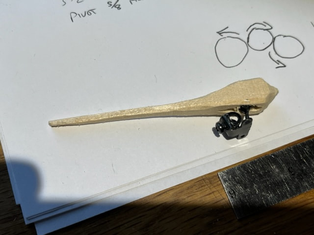
Here is my test cuckoo bird. I bought a cheap plastic cuckoo bird on line because I wanted the mounting hardware. The mounting hardware includes a set screw and also the pivot point. The bird pivots so that it can nod up and down when it chirps. The tail is long, as there is a lifting wire in the mechanism that lifts the tail to make the bird bob up and down when it chirps.
There is a small wire that goes through the wooden bird and through the mounting bracket and that wire is the pivot.
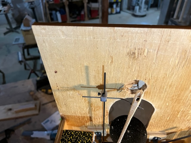
At this point I mounted the bird on the cross wire. I found that I needed to bend the cross wire that the bird is mounted to, in order to have the bird exit straight out the front door. I also made a small wire linkage and attached it between the bird mounting bracket (which has holes for this purpose) and the door. When the bird rotates forward this linkage opens the door in advance of the bird (and also closes the door when the bird retracts)
Top view of installed cuckoo bird mechanism
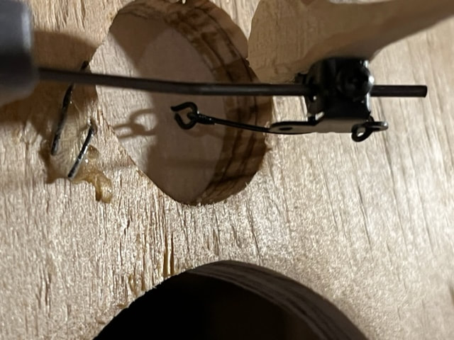
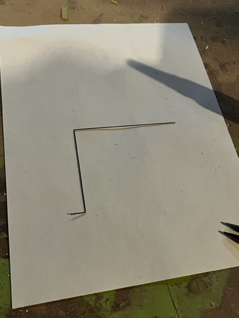
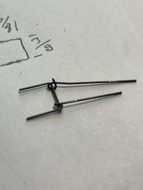
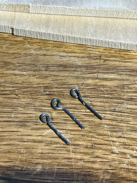
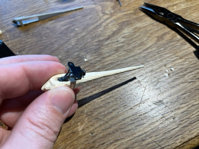
I fashioned this small-gauge steel wire to serve as the lifting wire that will lift the tail of the cuckoo bird. The lower left end of this wire will be pounded into the top of the bellows and the long upper right horizontal leg of this wire will rest just beneath the tail of the cuckoo bird. When the bellows raises, this wire will cause the cuckoo to pivot/nod up and down at the same time the bellows make to coo-koo sound.
Completed test-case for cuckoo clock.
I have run the clock through the hour and half hour cycles and everything works as it should! It is so fun to watch the movement move. The music starts and stops at the beginning and end of the song, the bird comes out its little door and the bellows make the cuckoo sound as the bird nods up and down, and the dancer platform rotates around. At this point I will measure everything up and get to work building my actual clock case.
Building the finished Clock Case
Now that I have proved out how the various components and linkages work and need to be aligned and spaced. I will measure the draft box, and get to work on the finished clock case.
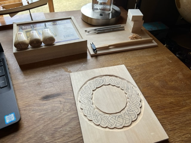
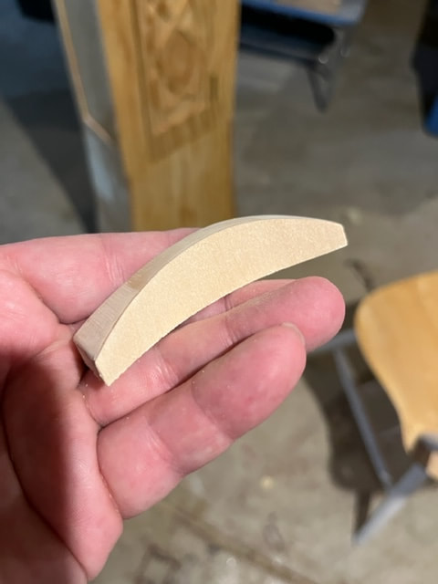
Carving a Celtic braid to surround the clock face:
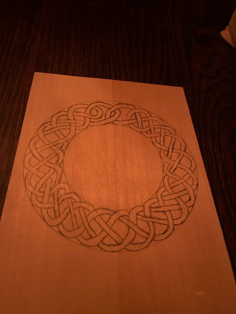
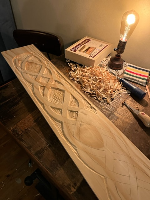
Fun little project before working on the case framework.....I carved a celtic braid into a basswood ring which will surround the face of the clock. This will not be a traditionally carved Black Forest Cuckoo Clock. I will be incorporating Nordic and Celtic themes.
1st I glued up a couple pieces of basswood to make a 1/4" thick sheet big enough for the ring, then I used a compass to draw the inner and outer diameter circles of the ring. With the inner and outer circles scribed, I drew the Celtic braid by hand, thus it is quite organic and not precisely repeated or spaced as the braid goes around. It is fun to draw these, the strands go over and under....though I did make an error in my sketch and went over when I should have gone under, a mistake that carried through and only noticed after I was done carving! It is a fun mistake I will leave in the work.
I began carving by carving the outer and inner perimeter of the braid.
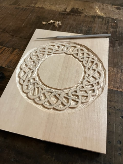
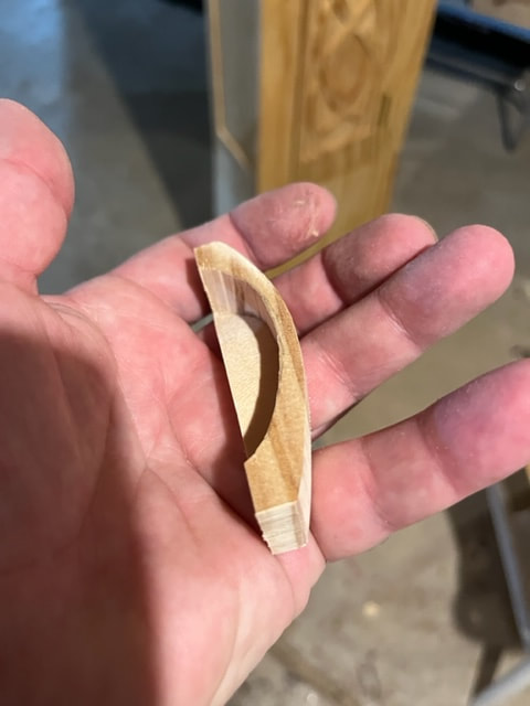
Then I used micro chisels to carve out the inside pockets of the braid.
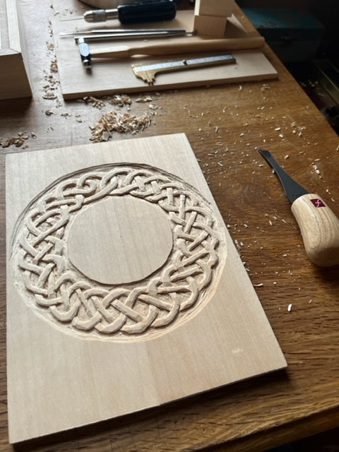
Next, I carved depth into the strands that go under the upper strands of the braid, and I carved rounded edges on all the braid strands.
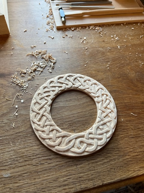
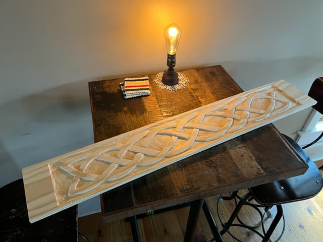
Lastly, I cut out the OD and ID of the ring with a scroll-saw and carved tiny radiuses onto the sharp rough edges left by the saw.
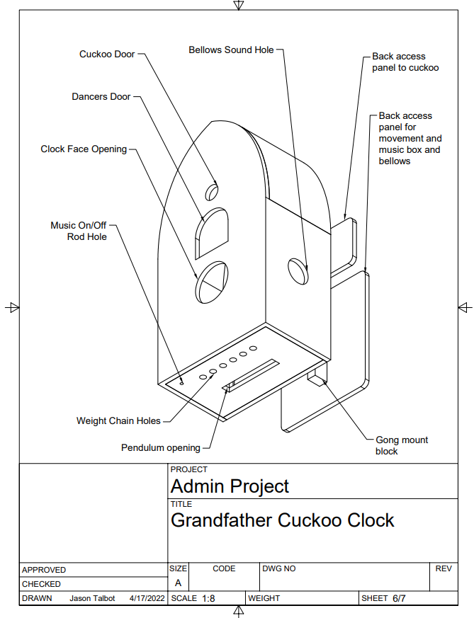
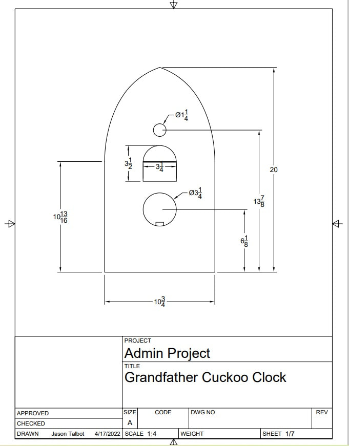
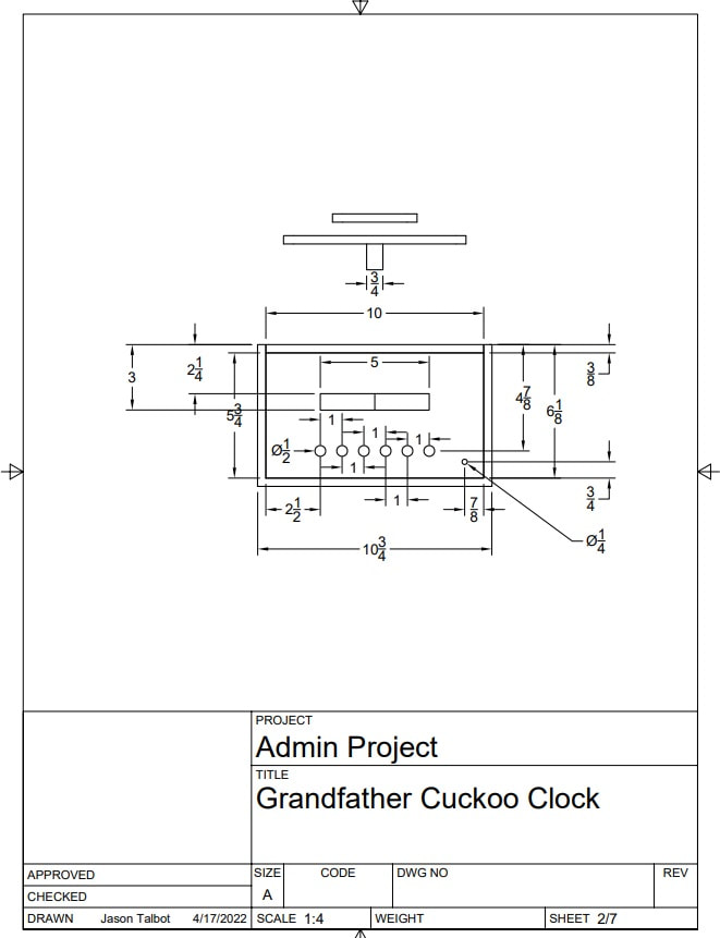
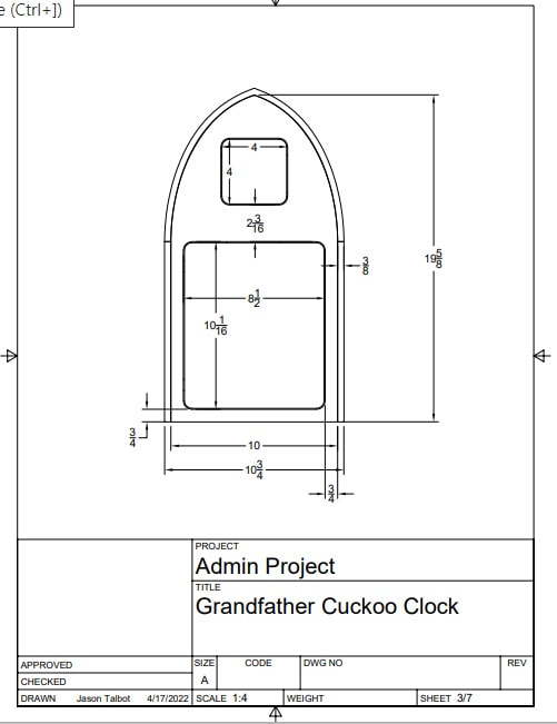
Regula 72 Cuckoo Clock Frame Dimensions
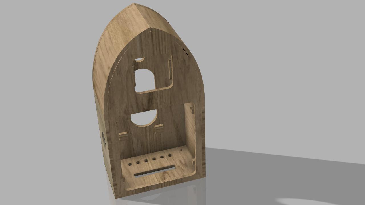
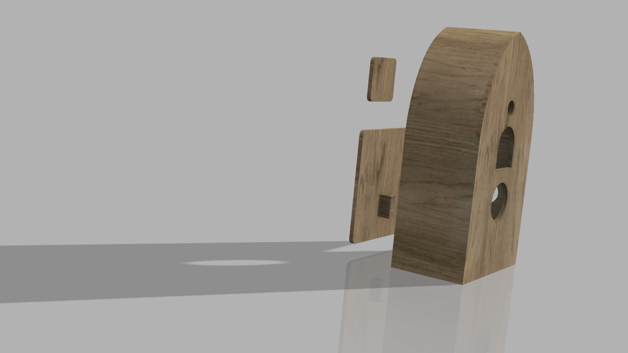
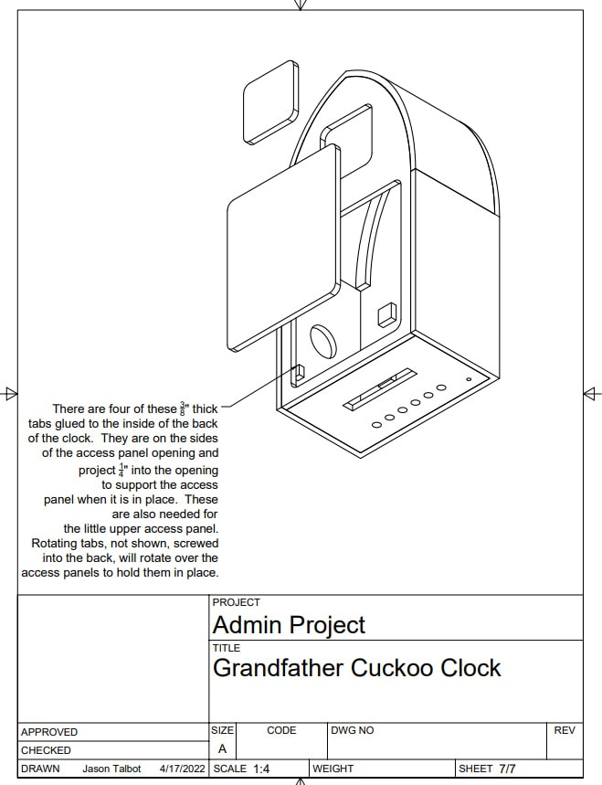
I measured my test frame and modeled it in Fusion 360 CAD. I will include two access panels on the back. Also, I moved the little back-panel-support-tabs to the sides so that they do not interfere with a screw-driver when installing/removing the movement-mounting-screws at the front face. Also notice that I will not cut in a side-slot for the music-on/off lever, but rather will install a vertical raise/lower rod which will link to the on/off lever and which will be accessible from below; thus there is a small hole in the bottom of the frame for this on/off rod to pass through.
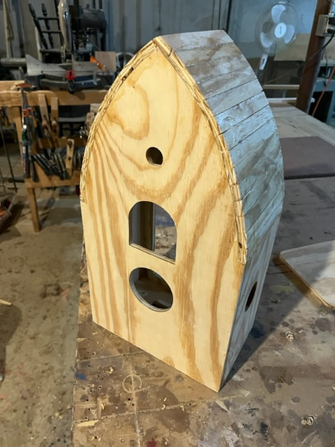
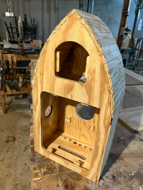
Making the head box frame for the clock
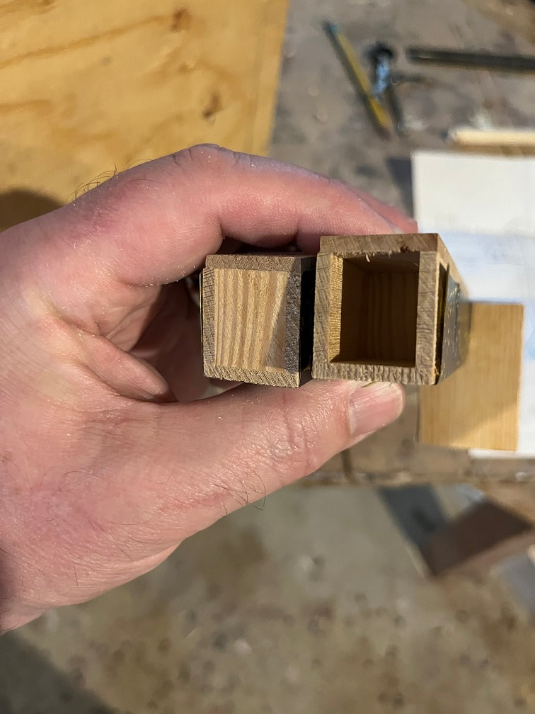
Built the frame for the clock from 3/8" plywood. I used plywood for the box-frame of the clock, because I don't want expansion/contraction of the wood messing with the alignment of the linkages. I will sheath this plywood frame in solid wood later. I raised the location of the cuckoo bird opening by about 1.5" (and I checked that the cuckoo actuator extended that high up, which it does). This box is glued together and held with pin-nails.
Building the Grandfather clock case out of pine
I thought pine would be a good choice for my attempted Nordic and Celtic themes, and pine is also a tree that grows in this area. The clock case will be clear pine with no stain, only tung-oil finish. The tall lower stand section of the clock case is solid clear pine. For the curved faces I am using planking to go for a ship's plank type look. I am using biscuit joinery for the joints. Next I will make a solid pine outer-facing for the upper clock case whose core if made from plywood.
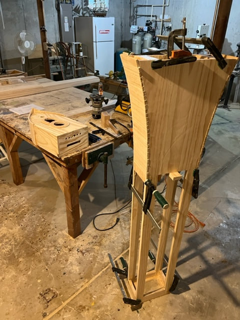
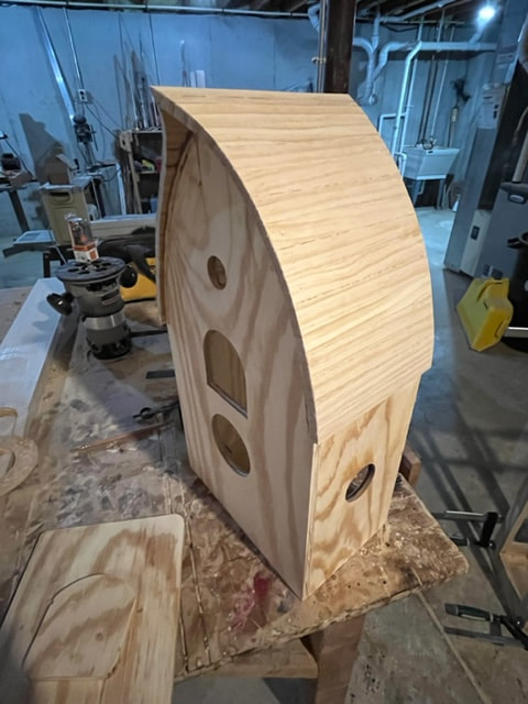
I planed clear pine down to 3/16" and made the sheathing for the top case of the clock.
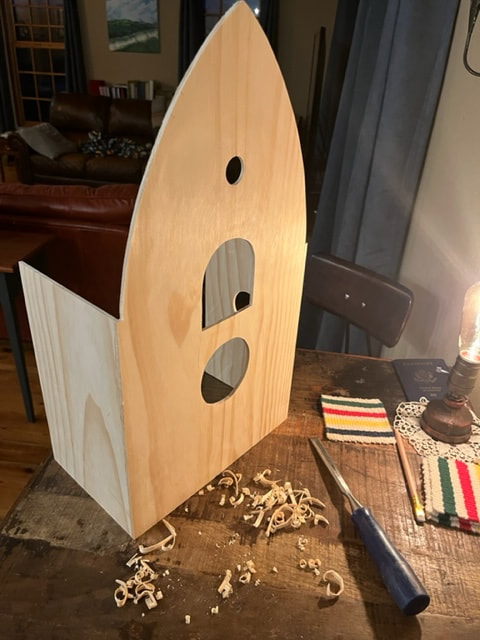
Drawing and carving the celtic braid on the front door of the clock.
Here is the finished front acces door, solid pine.
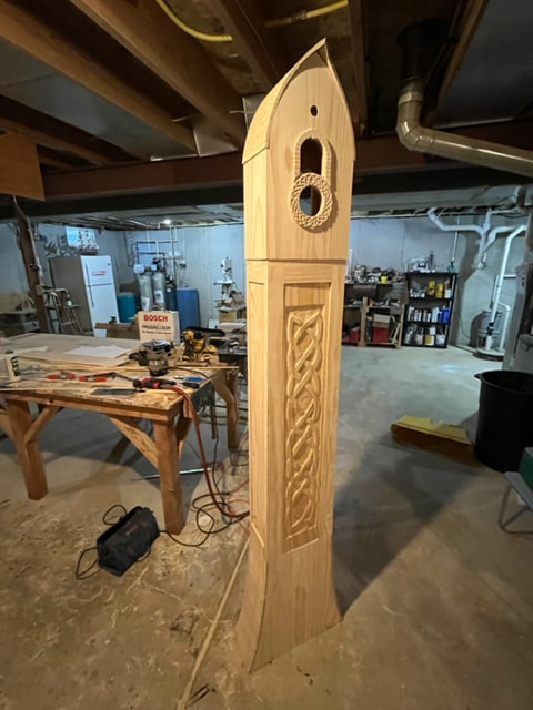
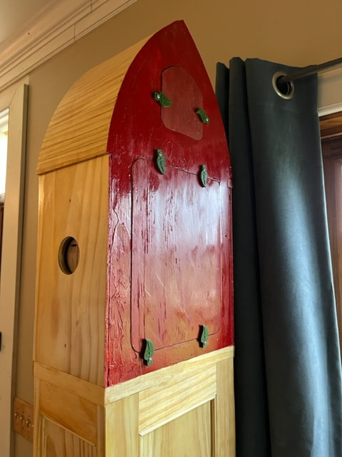
The top case is not screws on , it's just resting on the lower frame, but this was the first time I could get an idea of how it'll look.
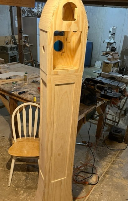
Here the floating solid pine panels have been installed in the sides and back of the clock case.
Close up of moldings that retain the floating panels.
Installing the movement, music-box, bellows, and cuckoo in the cuckoo clock case.
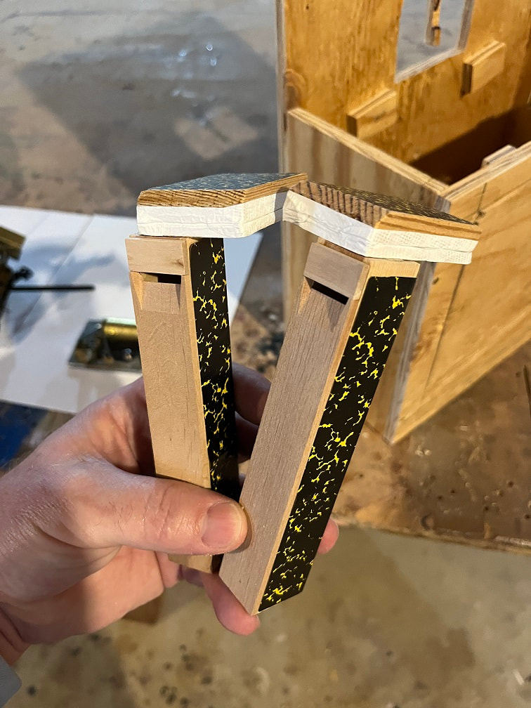
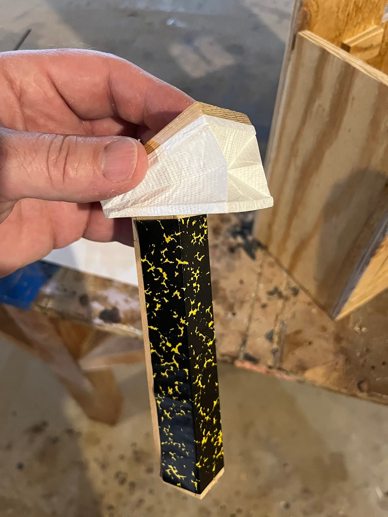
Well there certainly was some comedy when I went to install the mechanisms in the finished case. Most notably, even though I took all the time to build a test-case so that the final case would be built to the correct dimensions......my drawings were wrong and the hole in the side of the finished case (for the bellows sound) was way to low.. It was not in the right place. Oh the humanity. So after the whole test-case process, meant to avoid modification in my final clock, I still wound up needing to modify my bellows to get them to work in the finished case. I did not want to build a new clock case, and I did not want to fill and relocate the hole, so I built tall brackets, with a super-glued and rabbeted joint to the bellow top, so that the attachment eye was at the correct height from the movement to attach the linkage wires from the bellows to the movement. See photo below. Some poor clock-worker in the future will look at this and shake his or her head. Music box and gong are working perfectly. Bellows working perfectly through 2 days of cycles. The bellows hold-down brackets worked super.
NOTE: My original design was to control the on/off level by raising it or lowering it directly with the lever sticking out the side of the case. I decided against this in the final design and cut the lever short and drilled a hole in the end of it. I will attach a vertical rod to the end of the lever and will pull the rod up or down from inside the lower case to turn the sounds on or off. IT's dark in the photo but the shorter on/off lever with a hole in it, can be seen in the photos.
Problems with the bird
First the fun part. I carved the bird and added little wings and painted it like a Bluebird, which are fun local birds to see here in Wisconsin.
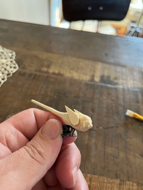
Carving in process, cuckoo clock bird that will be painted as a Bluebird.
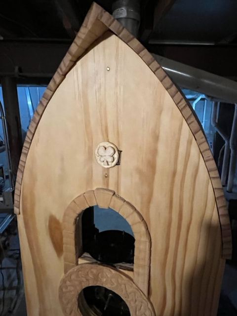
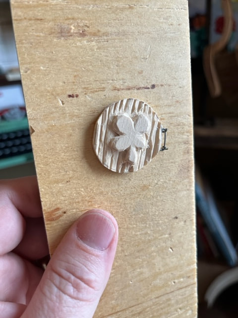
New four-leaf clover carved cuckoo bird door, installed with wee little wire hinges I made.
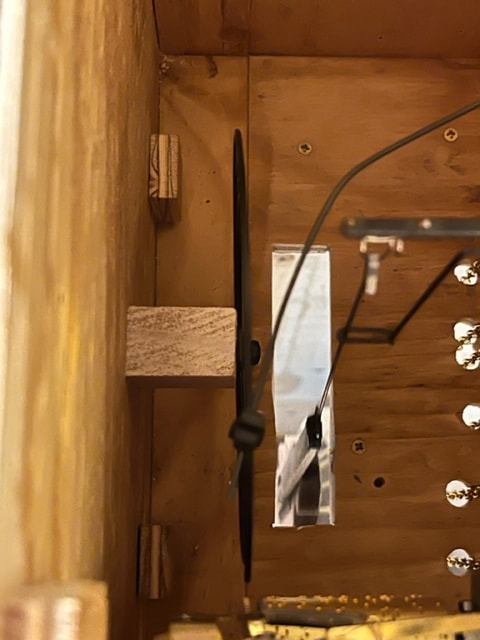
I carved and installed the little cuckoo bird door and at that point I was high-fiving myself all around town, and installed the pretty bird in the mechanism. Then, as I ran the movement through its cycle the bird would open the door and cuckoo-doodle-doo, but would not return home to its cozy nest in the clock and close the door behind it. I tried and tried making tiny tweeks and making sure nothing was binding, and I just could not get the cuckoo bird and door to close. The tiniest force, lightly blowing on it, would close it. I wanted to see if something was wrong with the spring on the front of the movement that should have been providing the force to return the cuckoo to his home, but that would have meant taking all the parts and movement out, and I decided against it. Maybe a bad decision. My solution will be another head scratcher for any future clock-smith. I added a tiny gauge piano-wire to apply a tiny bit of force to the bird mechanism to return it to the retracted position. This has solved the problem, but its not an "OEM" solution.
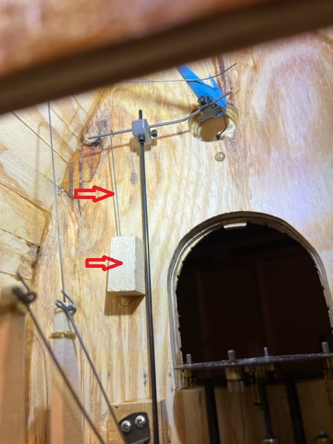
The arrows are pointing at the helper spring that I put in place to ensure the cuckoo retracts back after poking out the front door. The spring is a tiny gauge piano wire pressed into a wooden base-block and then linked to the cuckoo perch wire. This is unconventional but it fixed my problem and I will report back if it creates any problems in the future.
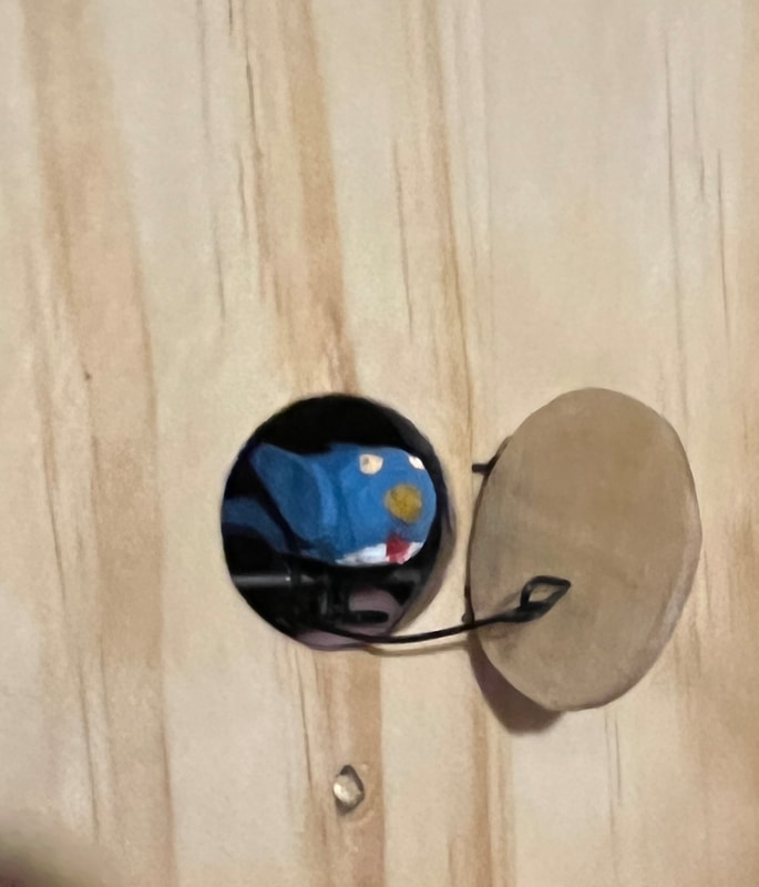
Here is Mr.Bluebird saying "Hello".
Case-front door work
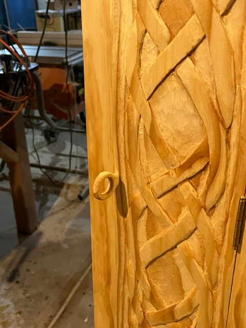
Hand carved a ring-shaped knob for the casefront door.
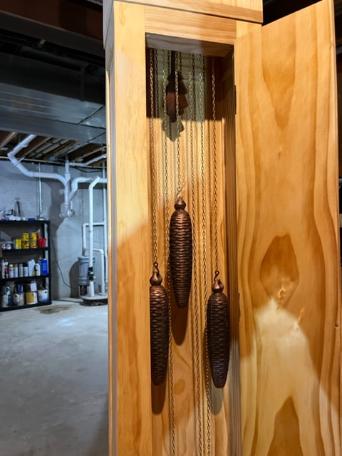
Pendulum and 3 weights visible inside the case.
Carving the cuckoo clock dancers.
I carved these out of basswood , which hardwood spheres for heads. These are based on my wife, two daughters, and I; so it will be fun to watch them dance around.
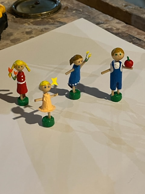
Hand carved cuckoo clock dancers.
Here is the little "balcony" I made to fit over the dancers platform so that the platform and gears are not exposed.
Top view of the balcony. In the finished pictures below, the balcony can be seen installed on the face of the case.
Finishing the cuckoo clock
4 hand rubbed coats of tung-oil. I completed the on-off mechanism. Installed the dancers. Finally, I brought the clock upstairs and put it in place. I used a long screw through the back of the clock into a stud in the wall to prevent someone from knocking it over.
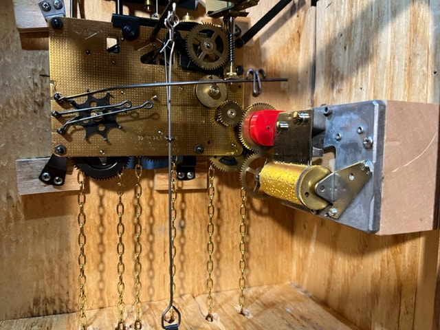
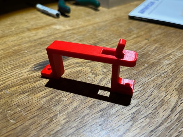
Final view of the inside of the movement case. Note the vertical rod with red fork that attaches to the on/off lever. This vertical rod extends down into the tall-case and pushing this rod up or down will turn the music on/off.
Here are the weights in the case, and one can see the on/off rod (with round loop/handle at the end).
Access panels installed and clock ready to be put in place.
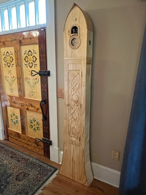
Completed grandfather clock with cuckoo-bird, dancers, music-box, cuckoo sound bellows. A very fun project indeed!