SCAMP Deck, Cabin (Veranda), Carlins, Gunwhales, Cockpit-Coaming, and Roof
With the bulkheads and seat longitudinals making up the start of the boat's frameworks, I added the initial structural members for the roof and deck; these initial roof and deck components consisted of sitka spruce beams running fore-aft near the centerline, to support the roof and foredeck. The mast trunk, which I had built as an assembly outside the boat, was also installed into the boat at this time. Details on mast-trunk construction are on the HULL page.
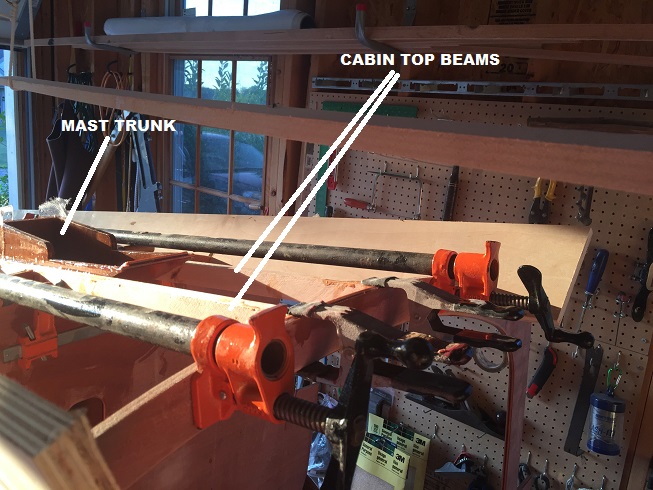
The cleats of the Argo are made of clear vertical grained fir. The cabin top beams and foredeck beams are made of sitka spruce. I precut the cabin top and deck beams, and glued them in place at the same time as the mast trunk assembly (which I had pressambled on saw horses).
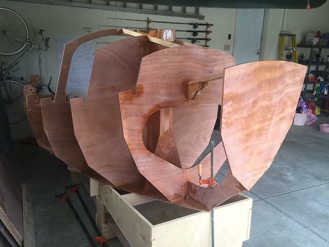
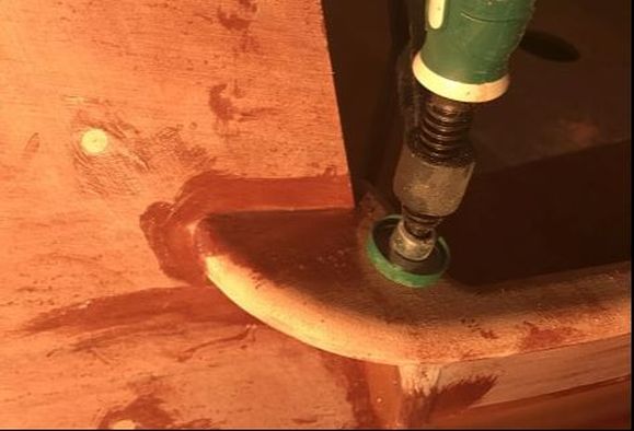
This photo shows long pipe clamps to port and starboard which are clamping the cabin-top-beams end-wise, and a central clamp which is providing endwise pressure on the foredeck beams. Two small clamps are compressing the mast trunk sideways between the cabin top beams, and two spring clamps are holding the cabin top beams down vertically in their pockets in the far aft bulkhead. The big boards you see running the length of the boat are temporary spacing template fixtures that will be removed after glue-up. they were provided with the kit and are very handy.
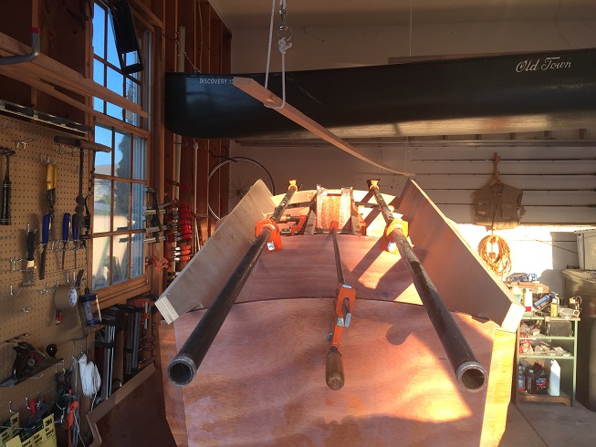
More clamping arrangement photos.
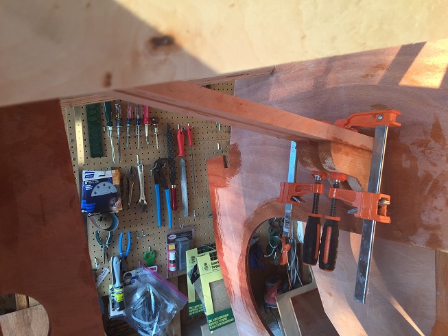
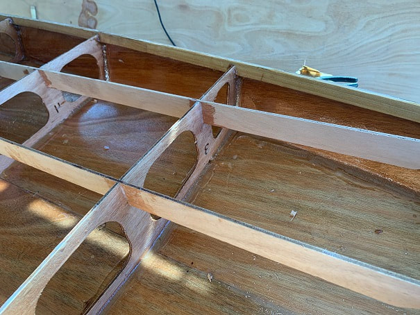
Small deviation from standard plans; I installed a couple gussets under the foredeck beams, they are epoxied, and filleted in place.
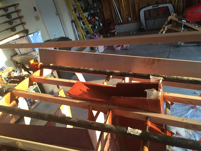
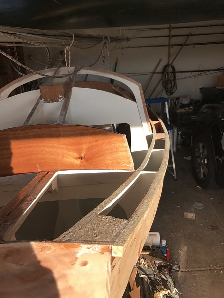
Clamps removed, showing mast trunk, cabin top beams, and deck beams installed
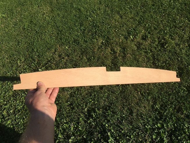
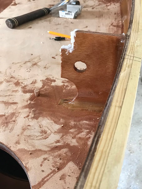
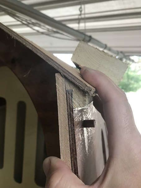
- The aft edge of the foredeck is supported by a piece of plywood that is epoxied onto B2, the piece is in the kit and is pictured below. I will modify this piece to fit on either side of my extra reinforced deck-beam-gussets.
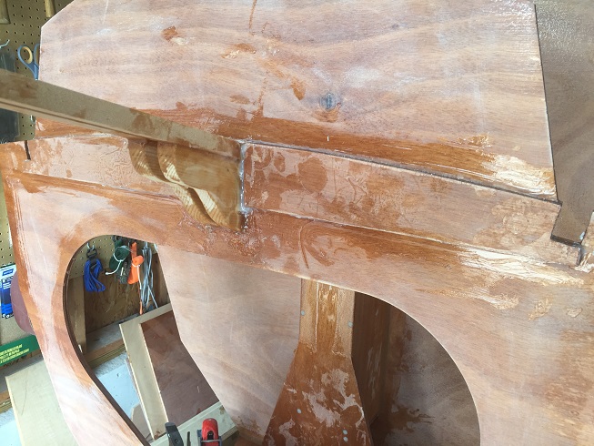
Foredeck aft edge support piece installed onto B2 with silica thickened epoxy. The top of this piece is scraped smooth and square so that the deck will fit well up against the bulkhead, and down onto its supports.
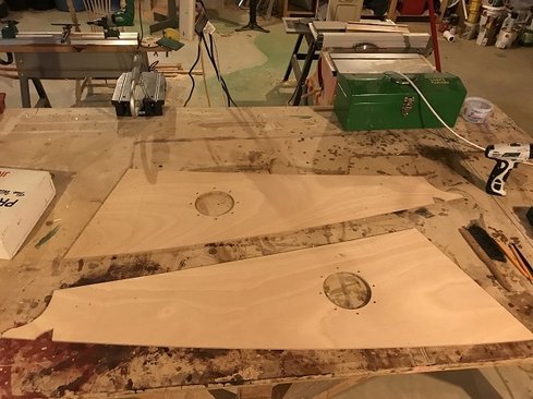
- It's been about a year since I worked on the deck or veranda areas. I have been working on the hull planks, cockpit, and footwell in that time. I am getting ready to install the seat tops, and after that I will install carlins and decktop, so I went ahead and glued up the deck pieces with thickened epoxy. See below.
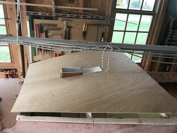
Gluing up the SCAMP deck
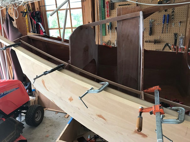
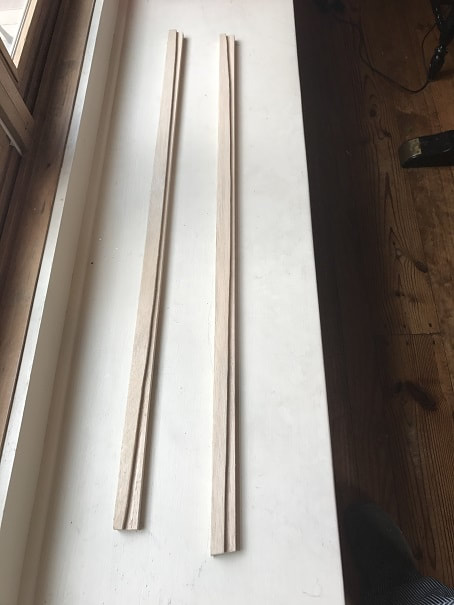
- The sole is installed and the cockpit is almost ready to have the seat tops installed, so I am preparing to attach carlins and gunwhales. I ripped them to the proper cross section from as nice as possible pine boards as could be found. I ripped carefully so as to remove as many knots as possible. I wound up with many 100% clear boards and a couple with tight knots.
- I have heard of quite a few SCAMP builders snapping these pieces as they bend them into place. I took one of my clear strips and clamped it into position on the outside of the hull, and I was able to do it without snapping, but boy o boy there was alot of force on there and I felt it may very well snap....or that I would snap a couple in the process.....so I decided to steam bend the carlins and gunwhales.
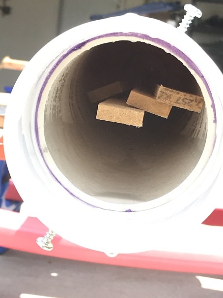
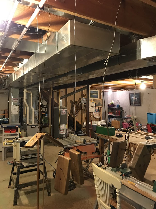
- Built a steambox out three, 6 foot (1.8m) sections of 6" (150mm) Sched 40 PVC pipe. Whipped up some fittings and a high temp hose onto the top of my propane burner and big pot. The far end of the steam box has two 3/8" holes drilled into it to relieve steam pressure. The entire assembly is glued together except the end cap where the steam enters the box....that end cap is held in place by two screws so that it can be opened up to put sticks in and out.
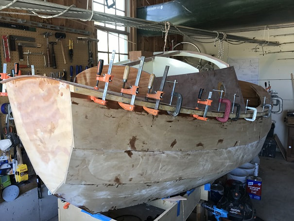
- Well, never having steamed wood before, I filled the pot up a little over half way and let-er rip. I put four sticks in, and steamed them for an hour and twenty minutes. Then I turned off the heat, and waited for steam to stop coming out of the steam exit holes. Then, with thick leather gloves, I removed the end cap and pulled the boards out. They were plenty hot. I immediately took them and clamped all four along the contour of the gunwhale on the port side of the SCAMP. It still took some force, but I was able to pretty easily bend and clamp them all in place, no snapped boards. Checked the water in the pot and I had boiled it down from a little over half full, to about a third full, so I refilled to a little over half and repeated the process for the starboard side.
- My plan is to leave them on there for a couple days and hopefully the curves will have set-in so that I can reinstall them with epoxy and screws later.
- SAFETY NOTE: You follow my actions and plans above at your own risk! I am not experienced in steam boxes, and am not a qualified steam box designer. Steam is dangerous; it can build up extreme pressures at burning temperatures, and an improperly built steambox could build too much pressure and a component of it could explode under pressure. Do not force steam into an enclosure without a way for the steam to safely exit the enclosure. Do not use materials in areas where they could start on for or melt. If you are using fire to heat the water, do it in a safe place where you wont start other nearby things on fire; probably best to do this outside. Have a hose or fire extinguisher handy. Use materials that can withstand the pressure and temperature. Do not open up pots, containers, or boxes that are under steam pressure.
- Photo's below
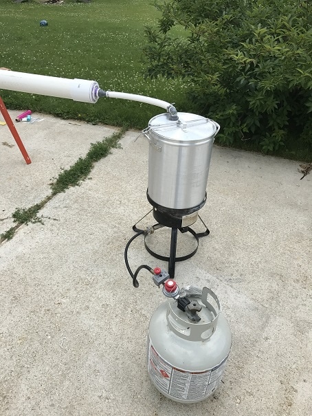
Propane fuel and burner, and a large aluminum pot generate the steam.
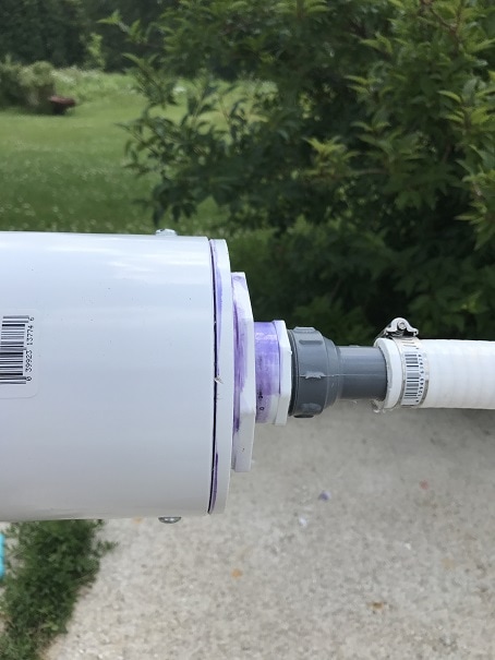
Fittings at the steam-entry end-cap of the steam box. The two screws that hold the cap in place can be seen on the top and bottom of the PVC pipe.
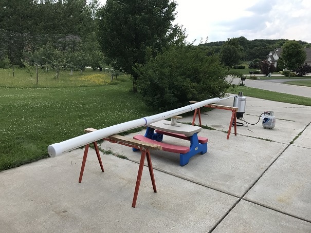
18 foot (5.5m) long, 6" (150mm) dia steambox in operation. The heat is deforming the PVC a bit.
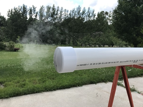
Steam exiting two 3/8" (10mm) diameter holes at the end of the steambox
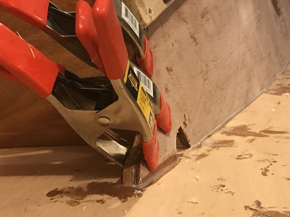
Gunwhales and carlins in steambox, ready for removal
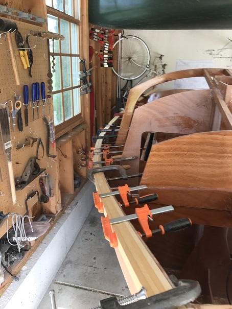
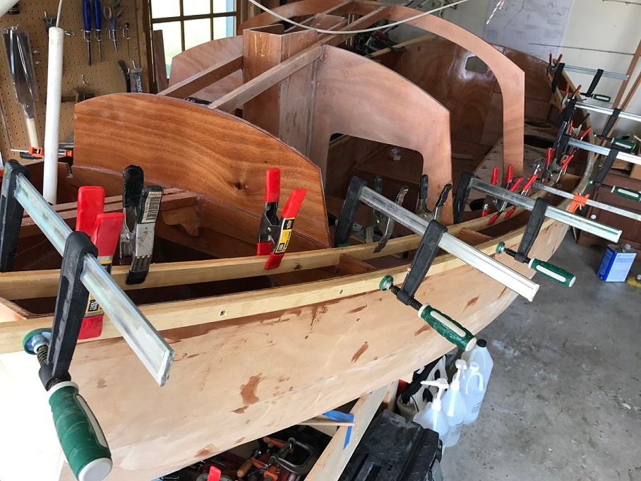
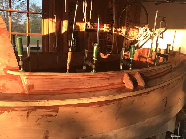
Gunwhales and carlins clamped in position after steaming, for the purpose of forming them to shape
Gunwhales and carlins clamped in position after steaming, for the purpose of forming them to shape
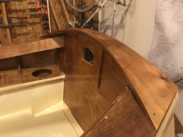
This was a good time to cut out the openings in the cabin sides for the deadlights. I predrilled the mounting holes oversize to fill with epoxy, and I also cut out the openings that will allow water to drain out to the sides from the front of the cabin.
Epoxy coating cabin sides
Installing SCAMP Gunwhales and Carlins
- The carlins are made from nearly clear pine. First I steam bent the gunwhales and carlins, and clamped them, 4 per side, to the port and starboard gunwhale in order to shape them. Detailed on steaming the gunwhales and carlins are further up on this page.
- I left them in place for a couple weeks (longer than needed, but I have been working on other things), and today I unclamped them. They had some memory of their old unbent ways, but the steaming had worked its magic, and they were very easy to fit to shape. First I clamped two of the pieces onto the gunwhale, and predrilled holes from the outide-in, and from the inside of the boat out, into the two gunwhale strips.
- Next I made a 5/8" x 1/4" x 14' strip of clear wood left over from a scrap from the mast, and I used this to practice trimming the carlins. I made a perfect fit template of this piece for the outboard carlin. I then used this template to saw the first carlin piece with the japanese saw. I clamped this piece in place in the boat and estimated how much longer the second carlin strip would need to be, and cut it accordingly (slightly oversize) and filed it to fit.
- Then I epoxy coated and installed the carlins with clamps. They wanted to slide up and down in certain places against each other, especially with the lubricity of the epoxy, so some vertical clamps were needed. I used spring clamps between the bulkheads to compress the carlin strips together.
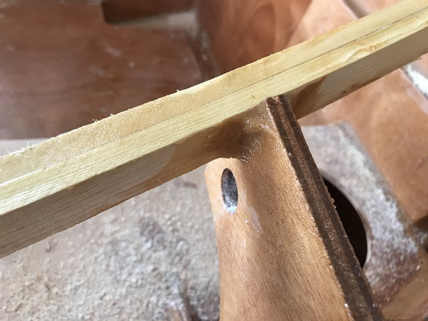
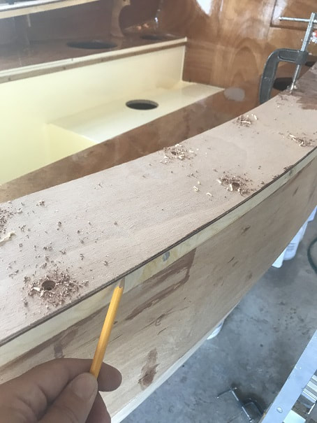
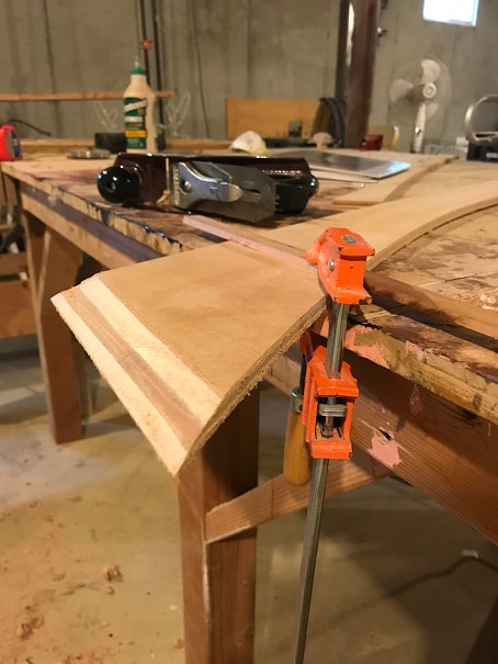
Gunwhale clamped in place, but not yet predrilled or epoxied. Here you can see the 5/8" x 1/4" template piece that I am working on for the carlins. This may have been overkill, but after all the cutting and steaming, I really didn't want to botch these pieces just before the finish line.
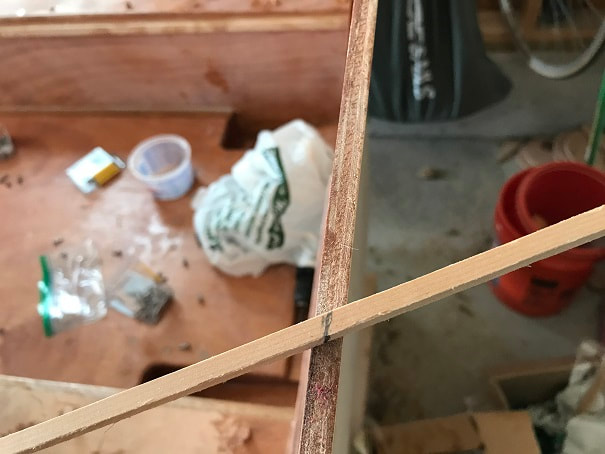
Marking the stern length of the carlin template piece.
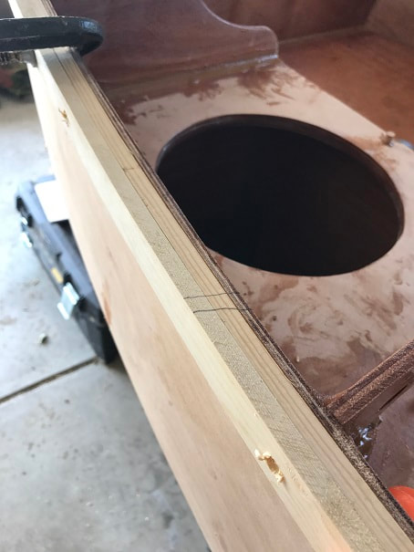
SCAMP gunwhale strips, predriled. Before unclamping the dry-fit gunwhale, I made some marks across both gunwhale strips and the hull plank, so that when I am installing them, I can quickly locate their correct position. The gunwhale is predrilled for screws from the inside through the plank and from the outside through the outer gunwhale strip.
Gunwhale is epoxied and screwed in place from the outside in and the inside out. You can see the thickened epoxy glue ready for installation of carlins.
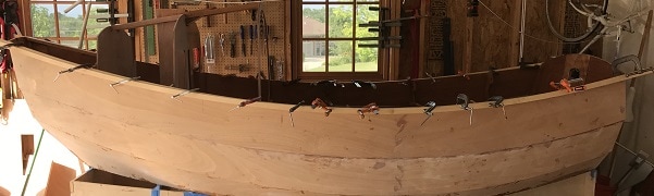
Drum roll......Tad Da!!! Gunwhales and carlins installed. I think it is a nice milestone to have these pretty curved boards installed.
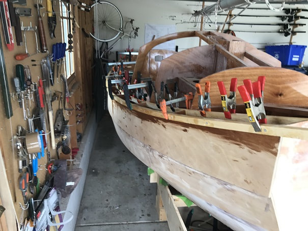
Starboard gunwhale and carlin installed.
Next I applied fillets between the bulkheads and the carlins.
Gunwhales trimmed at the bow (pictured) and stern.
- Now is a great time to add backer-blocks for cleats that will be installed through the deck. I will be installed three cleats along the starboard side and three along the port side.
- I used 1" thick sitka spruce that was left over from my mast, for the cleat reinforcement pieces.
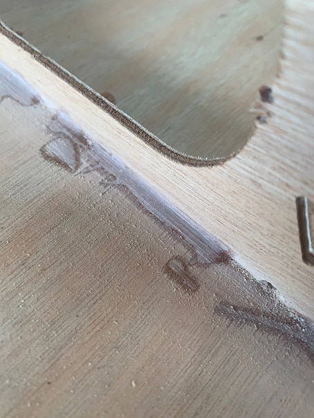
- I cut 5" x 5" pieces (125mm x 125mm) and then laid them in place over the gunwhales and carlins, and traced their shape from below. Then I cut out the shape on the bandsaw. I oriented the grain such that as the wood expands it will expand fore/aft, as I don't want these blocks pressing the carlins towards the centerline.
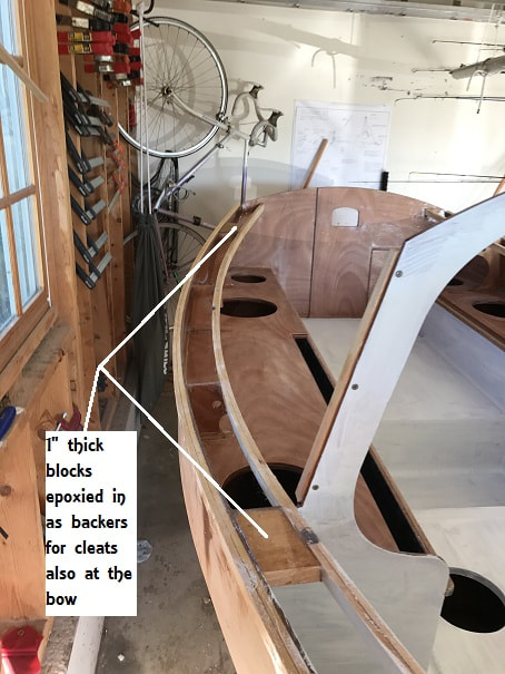
1" thick cleat backing reinforcement blocks are epoxied in-place between the carlins and gunwhales.
- The first coat of Petit EZ-Prime has been applied over epoxied wood that has been roughed=up with 80 grit sandpaper. Subsequent sanding will be with 120grit.
- Next, I attached wooden cleat strips on the aft side of B2, 3, and 4 which the sides will screw into. I made these cleats of mahogany, as they I think I will finish them bright. I epoxied them onto roughed up epoxied surfaces (do not epoxy them onto a painted surface) and my plan is to plane and file them to a taper that matchges the angle of the cabin wall, in-place, after they are attached. photo below. I noticed that the plans call for the cleats on B3 and B4 to be mounted on the fore side of bulkhead, I will have to modify the doubler aft of B4, but I will be good to go!
SCAMP cleats installed for the attachment of veranda/cabin walls. After they are dry, I wil file and plane them to proper angle/shape to fit the cabin sides, I think this tapering could possibly be easier done by measuring angles and tapering the cleats prior to installing, but I went ahead and glued 'em on, and will taper them in-place.
|
|
- Sanded primer with 120 grit paper, and applied a second coat of EZ-Prime
- Oddly enough, it was 52deg and rainy here in early August....I figured between the borderline low temp and rainy humidity, it was not a good day for painting so I shaped the carlins and gunwhales. With the curves, a spokeshave was to tool du jour, along with the Shinto rasp.
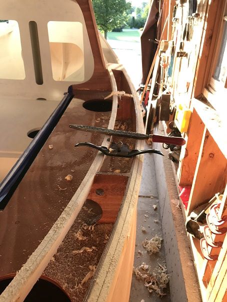
Finish-beveling and shaping the gunwhales and carlins on SCAMP. Spokeshave and Shinto rasp worked well for this rewarding part of building this boat.
Installing the SCAMP Deck
- I have seen decks installed with no-screws, with densely spaced clamps achieving solid even pressure to well epoxied surfaces. The design calls for optional fillets to the underside joints of the deck. As I thought about it I decided I should either epoxy and screw the deck down OR epoxy and fillet the deck down. I decided to epoxy and screw the deck down, but I will not be filleting the underside joints.
- Before installing the deck, I painted and varnished the cockpit interior, see cockpit page for details.
- Roughed up the under-side epoxy surface of the deck with 80grit.
- Laid the deck onto the boat and clamped it in place for a dry-fit-up, pre-drilled countersunk screw holes
Dry-fit of deck is in process. As shown in the photo, I scribed a line on the underside of the deck where it met the gunwhales & carlins. Then I removed the deck and trimmed to this line with a saber saw.
- Scribed a line on the deck where it overhung the boat, and trimmed this material off after I had removed the deck form the boat.
- Applied epoxy to the gunwhales, carlins, beams, and bulkheads, and then clamped and screwed the deck down. My screws are at about 9" spacings, but with how thin the deck material is, I found I needed to add clamps between these screw locations....so I would plan on screws or clamps about every 4.5".
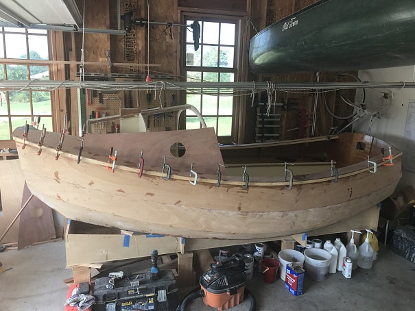
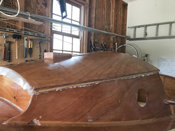
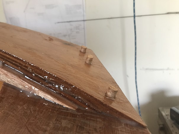
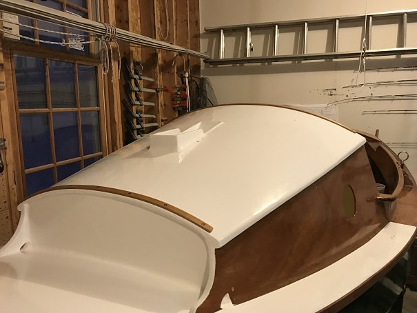
SCAMP deck, installed. The deck will be painted from the veranda forward, but stained from there aft, so I filled the forward screw holes with epoxy; the aft screw holes will be filled with mahogany plugs. The veranda/cabin side is just resting there, I haven't fit or installed it yet.
Installing Scamp Cabin Sides and Roof
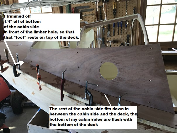
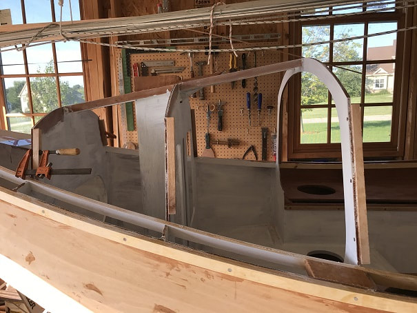
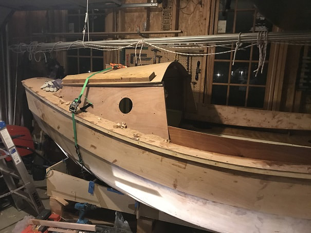
Dry-fit of Scamp Cabin Sides. Note that the bottom of the cabin sides forward of cabin, must be trimmed by 1/4" in order for it to sit up on top of the deck while allowing the balance of the cabin side to sink down to flush with the bottom of the deck. I dry fit and predrilled the sides.
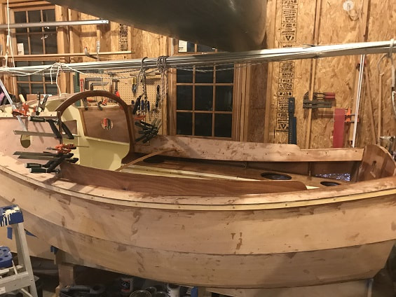
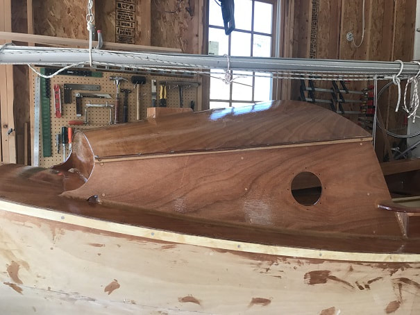
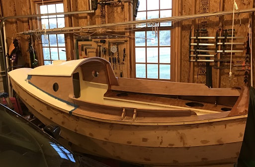
Epoxy glue and screws complete the installation of the cabin sides. The Argo has a deck and cabin sides, exciting!
- With the cabin sides attached, Iet the epoxy on the deck cure, and then removed all those clamps.
- Then set to work fashioning a good cleat to hold the roof to the cabin sides, and worked the parts to attach the cockpit coaming to the deck
SCAMP Roof Cleats
Here be a lot of text that will only be interesting to a person that will build this boat: There is a compound curve in the cabin top where it meets the cabin sides. It looks really nice. A cleat is needed to anchor the roof to the sides. There is a style decision to be made here. You cannot decide whether or not to curve the top of the sides: they are curved. You can decide whether or not to show a curve on the bottom edge of your cabin-to-roof cleats. As of the timing of my construction, when I installed the cabin sides full down to the bulkhead socket, the top of the cabin side height was short of the top of the bulkheads bay an inch or so. I would have preferred for the cabin side to be taller but no worries.
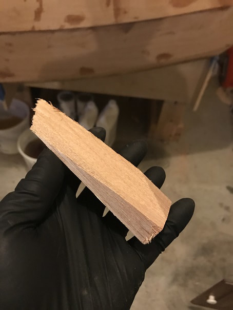
- I made solid Mahogany cleats with a custom curved rabbet, made quickly and simply with a chisel, in them scribed and cut to match the curvature of the top edge of the cabin side.
- This allowed me very solid purchase for screws, through the cleat, cabin side, and into the bulkhead cleats.
- I used 3/4" x 1.25" solid Mahogany cleat material.
- I think that curving the bottom of this cleat would be classy, but my piece of Mahogany was 1.25" wide, and in order to fit a screw in the ends, I did not want to trim it to a curve on the bottom edge.
- I am happy with the look and strength of these cleats, the tops will be shaped and tapered to match the roof, and the bottom of the cleats will remain straight-as-installed. I used a plane to round-over the outer lower edge of the cleats, prior to installation;.
Custom scribed curved rabbet in SCAMP roof cleats. Solid Mahogany 3/4" x 1.25" prior to planning the top edge down to match the roof.
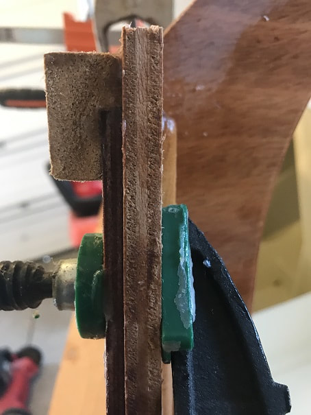
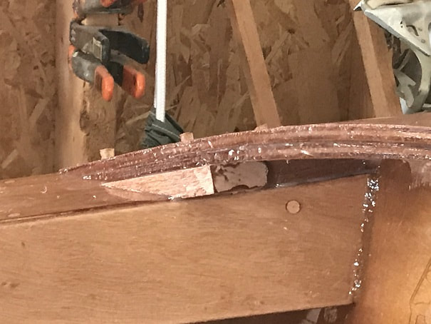
End view of the SCAMP roof cleat rabbet. I believe this epoxied joint will provide a strong cleat for roof attachment. It would have been easier if the kit provided a cabin-side that extended up to the full height of the cabin. This photo shows the cabin side doubler, which sandwiches my cleat in nicely, this all works out nicely.
At this same time, I beveled and scribed the cabin-side-doublers that are installed fore and aft of the bulkheads. Bevel the edges, then mark the outer dimensions of the pieces with a pencil. Cut on a scroll saw.
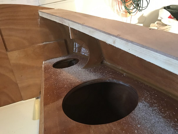
SCAMP fore-cabin-side-doubler being epoxied in place. I have cut matching scupper holes in both these pieces. Looking at the plans, I think it is absolutely worth it to spend the time to build these limber holes into the SCAMP to allow water to drain from the spaces forward of the doghouse.
Thickened epoxy glue-up of SCAMP "Argo" Cabin/Roof cleats. You can also see the clamp-up of the cabin-side doublers, fore and aft.
Here you can see the tight joint between the curved rabbet of the roof-top cleat and the cabin-side. The aft cabin-side doubler can also be seen being clamped into place.
SCAMP roof cleats installed and planed and beveled to shape. Here you can see the rabbeted cross-section of my roof cleat. There is plenty of depth for a 1" (25mm) long screw, which is what I will be using to secure the roof to these cleats. The cabin-side-doubler can also be seen in this cross-section.
SCAMP Sailboat Cockpit Coaming Installation:
Serious bicep (for me) workout, using the Shinto rasp to prepare an even and straight surface along the carlins and deck and bulkheads, for the cockpit coaming.
The pre-cut pieces fit great, with only a bit of trimming; quite impressive: well done SCAMP designers!. So here is the dry-fit of the cockpit coaming. I cut a compression-stick which was really needed at the point of maximum width, after that the coaming falls into place nicely and I found that clamps were needed about a foot from the stern for the dry fit. I then predrilled countersunk holes through the coaming into the carlins.
Here are the cockpit coamings fully installed. Time for some cheese and a fine beverage,
- Next , I plugged the holes with face-cut mahogany plugs and sawed them flush after the epoxy glue was dry.
The kit came with two little 9mm plywood triangular filler pieces to tie the foreward end of the coaming into the cabin side. I wanted something a bit thicker so I made these pieces out of solid mahogany. Exposed edges are rounded over.
It fits perfecto. I couldn't find a good clamping solution, so I predrilled two holes for brass nails into this little coaming piece and the nails held the piece in perfectly for the glue-up. I will leave them in-place.
Cockpit Coaming Cap and Oarlocks on the SCAMP "Argo"
- I had read a comment from Simeon on the SCA Scamp Message Board in which he advised a 1/2" round over on the interior of the cockpit coaming cap, for comfort when sailing.
- To achieve this, I will utilize the design below. It is important to use a 1/2" thick piece for the under-cap support piece. It bend well without steaming, and will provide a ample platform for the attachment of the cap itself. Thicker than 1/2" would require steaming, I think.
- Previous experience installing and using oarlocks on sailboats lead me to believe that additional structure would be required to make the oarlock stout enough where it is designed to be installed on top of the coaming. I do not think the unreinforced standard cockpit coaming will hold up to the significant forces that will be seen by the oarlock.
- I created 2 solid mahogany gussets, shown below, per side, and pinned/epoxied/filleted them into place at the oarlock location to provide additional strength.
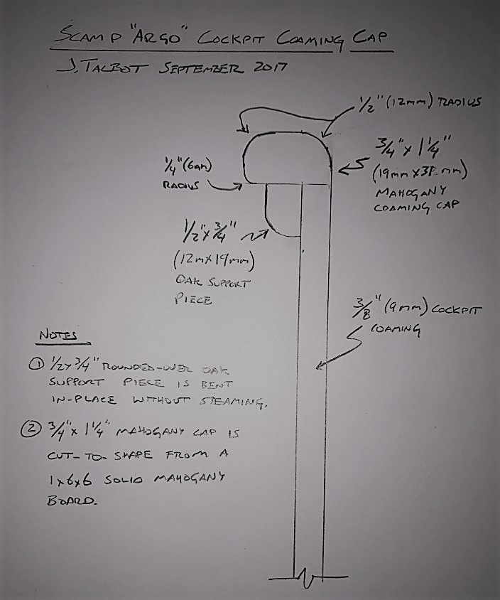
Drawing of the cross section of the cockpit coaming cap on the SCAMP Argo.
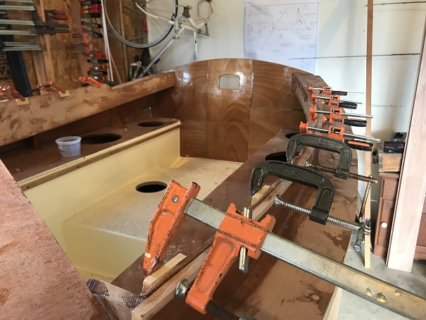
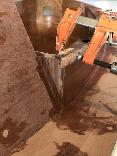
Cockpit Coaming Cap support piece is glued in place with thickened epoxy and clamped into position.
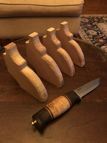
SCAMP Argo Oarlock reinforcement gussets, with edges carved using my Helle knife.
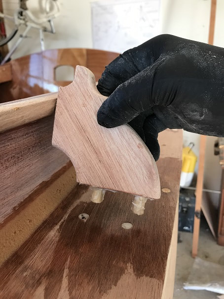
Oarlock "flying buttresses" as I called them, showing the hardwood pin connections on the deck. I cleaned up that coarse fillet with a brush and fresh epoxy before it set.
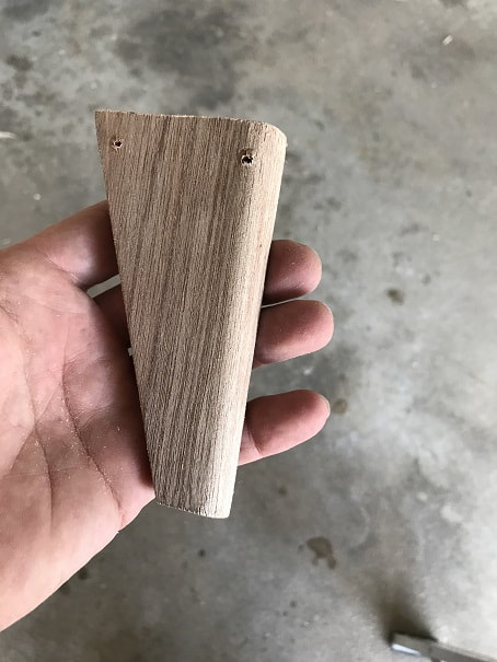
SCAMP Cockpit Coaming Cap, cut from a 1x6x6 piece of solid Mahogany.
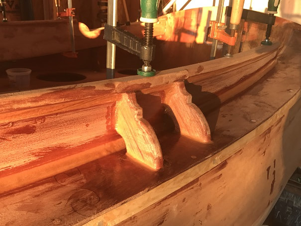
SCAMP Oarlock reinforcement pieces installed. Notice the square edge left on the coaming cap in the location where the oarlock will be installed.
Forward end of the cockpit coaming cap. Cut and shaped to overhang the coaming and tie into the cabin side.
Complete cockpit coaming cap assembly.
SCAMP Roof Installation
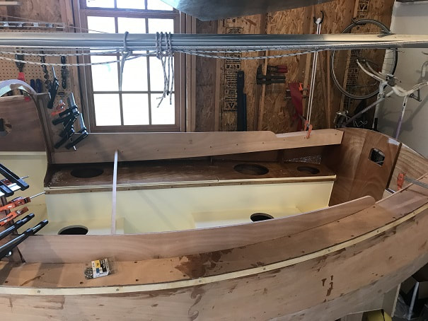
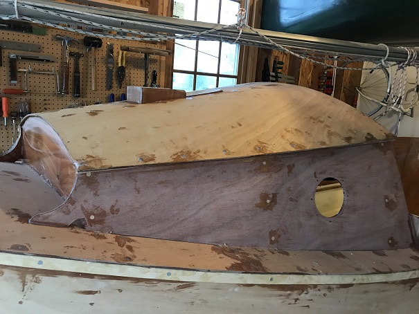
SCAMP rooftop, shown flat on top of the bulkheads. I needed to trim the aft edge of the mast-box-ramp a bit with the pull-saw in order to have the roof top fit over.
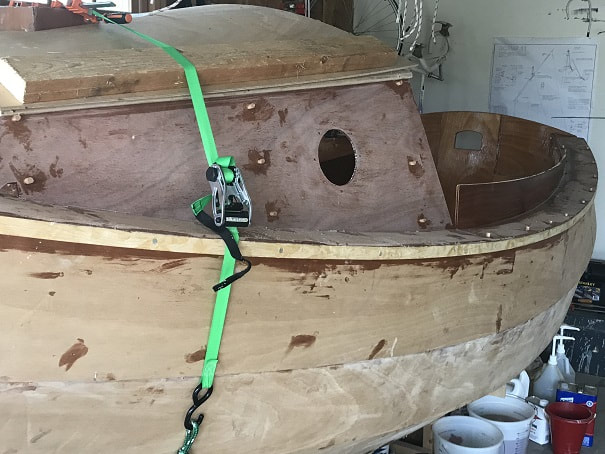
I used a ratchet strap and a couple 2x4 scraps to bend the rooftop to shape. I had 4 days coming up when I knew I wouldn't be working on the boat, so I bent the roof down and left it. No glue or screws at this point, just bending it to shape.
Screw holes in brightwork locations have been plugged with face-cut mahogany plugs.
- Next I glued and screwed the roof down. I mixed thickened epoxy and applied it to the top of the roof support members
- Then I set the roof back in place and screwed it down. I did not use the ratchet strap during final installation, just worked screw-by-screw around from side to side and down the length, and it worked out easy. Side-note, I have been using slow-set epoxy for this build, and I would recommend it for this step. I haven't found a need for the fast-set stuff....then again, I am not in a rush.
SCAMP roof glued and screwed down. The roof sides are protruding a bit over the cleats, which is good; I will trim and flush those up later. Screw holes filled.
- Used the Japanese saw to trim the roof up close to the roof cleats
- Then Shinto rasped and sanded sanded sanded the deck and coaming and roof.......
- Filleted cabin sides and fiberglassed cabin top (I will not be fiberglassing the cabin sides and deck)
- 3 Coats Epoxy on all roof and deck and coaming surfaces
Epoxy coating roof and deck
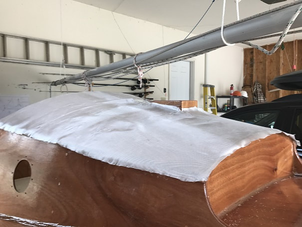
Cutting fiberglass for SCAMP cabin top. I left enough to overlap the side cleats and to go up the mast box a bit.
I used a 6" wide plastic spreader to distribute epoxy over the fiberglass, which worked great; the fiberglass is wetted-out over the top and along the side cleat faces. I will trim the excess fiberglass when it is still "green" ie not fully cured and still easily cut-able...at this temperature, moisture and with slow-set epoxy, this will be in about 8 hours.
Coaming fillets, cabin side fillets are done, and 3 coats of epoxy are on the whole deck roof, cabin, and coaming. Mast box is sanded, protruding edges rounded over, and filleted to roof.
Scamp roof doubler, being clamped in place. I needed to trim this piece to fit.
SCAMP Transom Cap
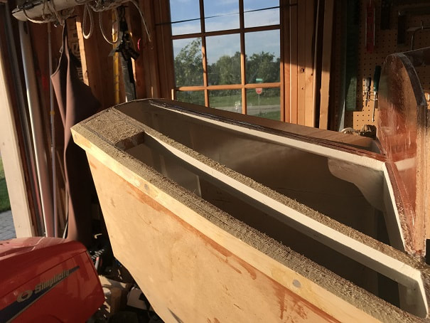
- Scamp features a transom cap, with a partial width doubler at the forward edge of the transom-cap. A multi-width and height space results, between the deck top and the bottom of the transom cap pieces.
- I elected to shape solid wooden pieces to fill the void, to prevent it from becoming an area where dust and bugs or even worse...water and ice could hang out. I shaped two pieces for the starboard side of the transom cap, and two pieces of the port side. I shaped these filler pieces from mahogany.
- I cut the big taper into the mahogany blocks of wood with a Japanese pull saw, then traced and cut them in plan-view with a little band saw. Finished it with the Shinto rasp. Made quick work.
Transom cap pieces beveled with a sharp plane.
Shaping the SCAMP transom cap filler block.
Here, the main transom cap is screwed down with three screws on the port edge, and the screws on the starboard edge. The main filler blocks pictured above are in there with epoxy slopped all over them. The little transom doubler has been fit and pounded into place also.
Next I quickly cut out these little wedges to fill the remaining void under the transom cap doubler. Cut with Japanese pull saw from a piece of mahogany.
Transom cap screwed on, doubler pounded in with solid compression and epoxy-squeeze-out between doubler and cap, and the deck-to-doubler-filler wedges are pounded in place. I will trim everything flush after dry-up. My boat now has solid wood filler between the deck top and the transom cap. A solid epoxy filler would work well also in this void, but it'd be a large volume of epoxy. Screw holes have been plugged with wood plugs and will be cut flush and sanded later.
Port side transom cap and filler pieces. The filler piece will be cut flush with the front edge of the transom cap.
Painting SCAMP Deck and Roof
- Deck, cabin top, sides, are all sanded and ready for paint. Fillets are not perfect, but I'm moving on.
- Vacuumed, taped off area to be painted, and solvent washed with Pettit 120 brush thinner
- Applied Pettit EZ Prime
- Sanded 1st coat primer with 120grit, solvent wash with Pettit 120 brushing thinner, applied 2nd coat EZ Poxy Primer
- Sanded 2nd coat of primer with 120grit , solvent wash with Pettit 120 brushing thinner, mixed Pettit EZPoxy Performance Enhancer 3021 with Mediterranean White Pettit EZPoxy, and applied 1st coat of finish paint.
- Sanded 1st coat of finish paint with 220 grit, solvent wash with Pettit 120 brushing thinner, mixed Pettit EZPoxy Performance Enhancer 3021 with Mediterranean White Pettit EZPoxy, and applied 2nd coat of finish paint
- Sanded 2nd coat of finish paint with 220 grit, solvent wash with Pettit 120 brushing thinner, mixed Pettit EZPoxy Performance Enhancer 3021 with Mediterranean White Pettit EZPoxy, and applied 3rd coat of finish paint
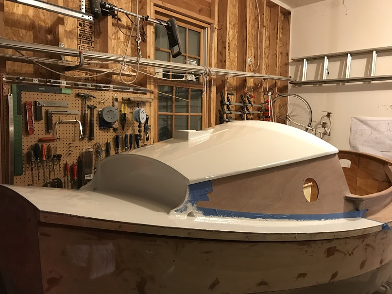
Pettit EZPoxy, Mediterranean White, applied to roof and foredeck.
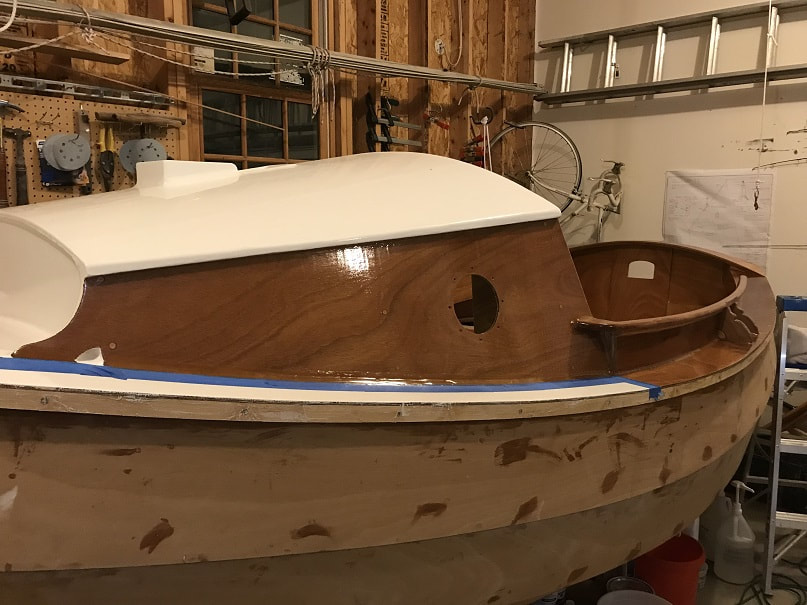
Next, I got the brightwork. The cabin sides, deck, cockpit coaming, will all get 4 coats of Epifanes High Gloss Spar Varnish, over the 2-3 coats of epoxy already applied.
- Sanded all pieces to be varnished with 120grit, solvent wash/tack cloth with Pettit 120 brushing thinner, then applied a thin coat of Epifanes Marine Varnish with a Purdy XL semi-rigid brush. Especially on the vertical surfaces such as the cabin sides, the coat must be very very thin, otherwise it will sag as it dries.
- Sanded with 120 grit between 1st and 2nd coats of varnish, solvent wash before varnishing. Then 220 grit sanding between 3rd and final coats.
- I pour the varnish through a conical paint/varnish strainer each time to keep it contaminant-free.
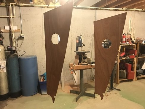
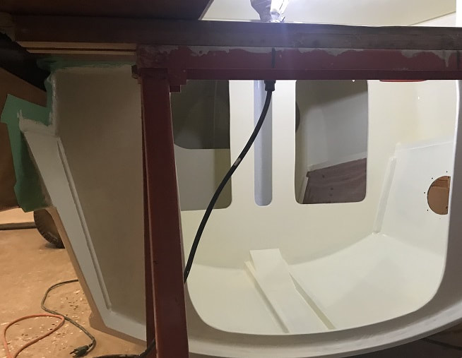
Retrofitting the original SCAMP Bulkhead 4 opening to the new MKII Design
It is October 2017 and it seems the SCAMP design has received some relatively minor, but potentially quite handy, tweeks. From what I gather, the new design includes 1. A footwell (I have already custom built one into my MKI SCAMP kit build) 2. slightly wider seat-tops (I will sail the boat first before making any seat-width modifications) 3. A smaller opening in B4 between the veranda and the cockpit.....this I like, and I just retrofitted/modified my MKI SCAMP to this new Bulkhead 4 concept. See details on that below. I welcome the new MKII upgrades and ideas from the designers, I think they can be made by anyone with a MKI that so desires. The original design is a beauty, upgrade if you want, or enjoy the wonderful original design! All design changes are a compromise as we all know....the original design of B4 may be better for those who day sail in light wind and want easy open access and views from the veranda. Now on with how I retrofitted B4 on the SCAMP "Argo".
Potential benefits wider "walls" on the port and starboard side of the opening into the veranda/cabin area are as follows:
1. If the boat is on its side, these walls will allow less water to enter the boat than the original larger opening into the cabin.
2. The more enclosed Veranda should provide a bit more shade/protection from the elements when one sits in the veranda
3. Sitting in the cockpit, facing aft, one can lean up against the new wider surfaces of bulkhead 4 at the forward end of the cockpit seats.
4. If I don't like it, I can always cut it back to the MKI design.
STEPS:
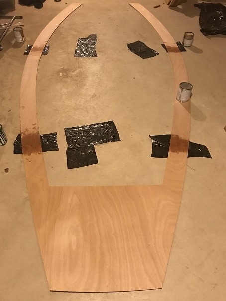
1. Cut out a slightly oversize piece of 9mm thick Joubert Marine Grade Okuome and clamped it in place on the forward face of B4.
Potential benefits wider "walls" on the port and starboard side of the opening into the veranda/cabin area are as follows:
1. If the boat is on its side, these walls will allow less water to enter the boat than the original larger opening into the cabin.
2. The more enclosed Veranda should provide a bit more shade/protection from the elements when one sits in the veranda
3. Sitting in the cockpit, facing aft, one can lean up against the new wider surfaces of bulkhead 4 at the forward end of the cockpit seats.
4. If I don't like it, I can always cut it back to the MKI design.
STEPS:
1. Cut out a slightly oversize piece of 9mm thick Joubert Marine Grade Okuome and clamped it in place on the forward face of B4.
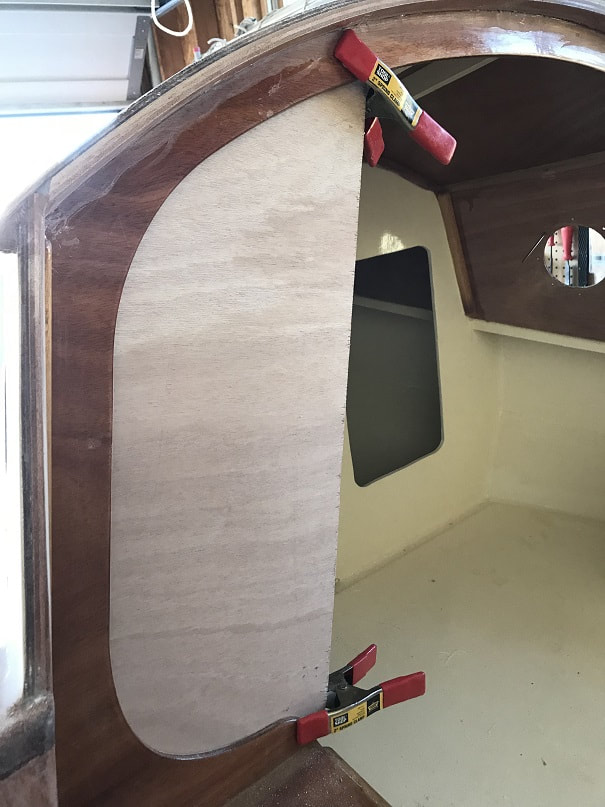
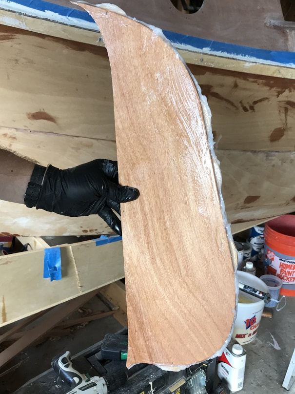
2. Traced the exact profile of the existing B4 onto the new plywood filler piece.
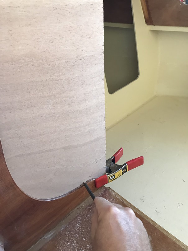
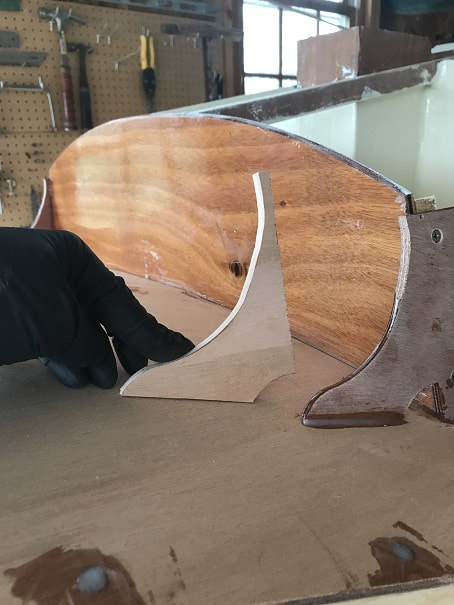
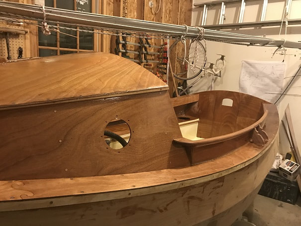
3. I cut out the profile of the existing B4, and then hand drew how I wanted the new opening to look, slight belly in the opening and then a large radius at the top where the filler meets the existing B4. I wanted it to look kind of organic and with some curves. Here is the first piece, it is close tolerance enough that when I put it in place , it stuck. Liking the way it looked, I used the first filler piece as a template and traced out and cut a second one.
4. Then I marked out locations for five (5), #20 size biscuits, 1 on the top edge, 3 on the side edge, and 1 on the bottom edge, of each filler piece. Then I cut in the biscuit slots in the filler pieces and in the existing B4. Took some fancy work with my biscuit joiner on some of the inside curves of B4, but got 'er done nicely.
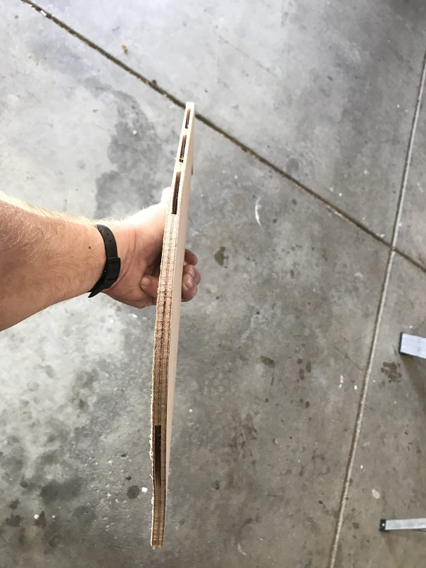
5. Then I sanded B4 down to bare wood and sanded a bevel into the face of all pieces where the joint is. I will fill and fair this beveled space with thickened epoxy for joint strength and for a smooth finished surface.
6. Coated the filler pieces on all sides and edges and in the biscuit slots, with unthickened epoxy. Coated the edges of B4 and the biscuit slots in B4 with unthickened epoxy. Then I thickened the epoxy with silica and liberally applied it to the biscuits and joints.
6. Coated the filler pieces on all sides and edges and in the biscuit slots, with unthickened epoxy. Coated the edges of B4 and the biscuit slots in B4 with unthickened epoxy. Then I thickened the epoxy with silica and liberally applied it to the biscuits and joints.
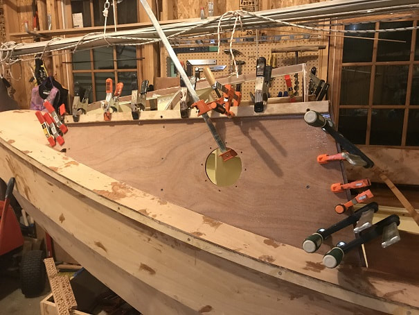
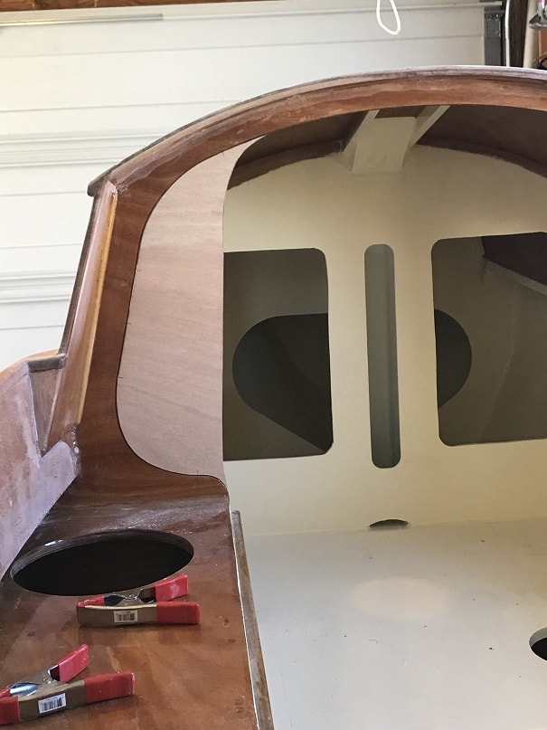
7. Pressed the filler pieces into position and they compressed and stuck in place perfectly, whew. The biscuits held them in place, as did the tight fit. The biscuits also did a nice job of aligning the filler pieces in the same plane as the existing B4.
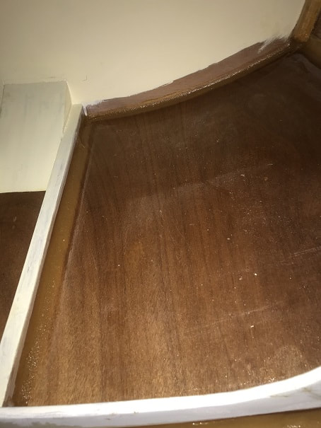
Microbaloon thickened epoxy used as fairing compound over the joints.
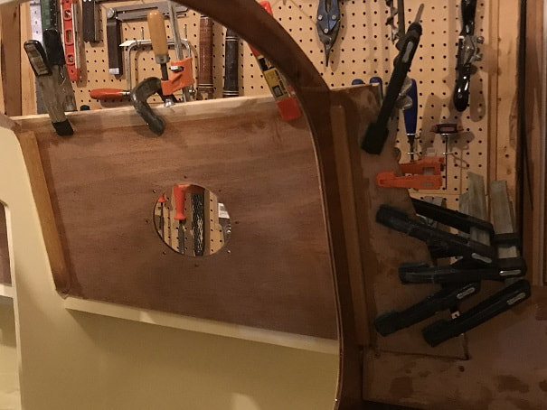
Sanded joints smooth and applied a coat of EZ Prime.
- At this point I called in the crew and we flipped the boat over so that the hull was facing up. Details and video of this are on the hull page. With the boat flipped over I will complete the filleting of the roof joints in the cabin, and also the transom to transom-cap joint. After the bottom is all done and painted, I will flip it back over and install hardware.
With the boat flipped over, I sanded joint areas with 80grit sandpaper, and applied nice fillets. At this time I also applied fillets to the transom-to-transom-cap joint.
I made 3/4" thick white oak backer plates, with holes predrilled, for the mounting of the cleats on the roof, and some padeyes which will be mounted in the cockpit. I am varnishing those here, along with two thin strips which will be the roof top chafe protection strips. I use straightened out hangers with hooks bent into each end to suspend small work like this from the ceiling during finishing.
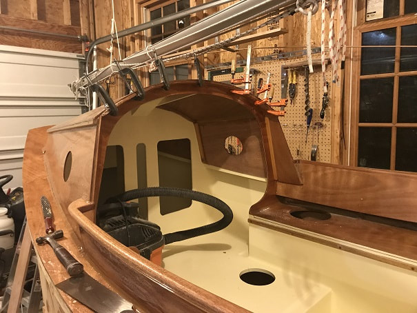
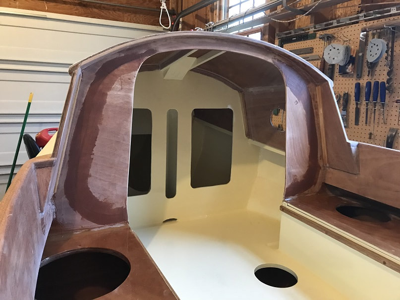
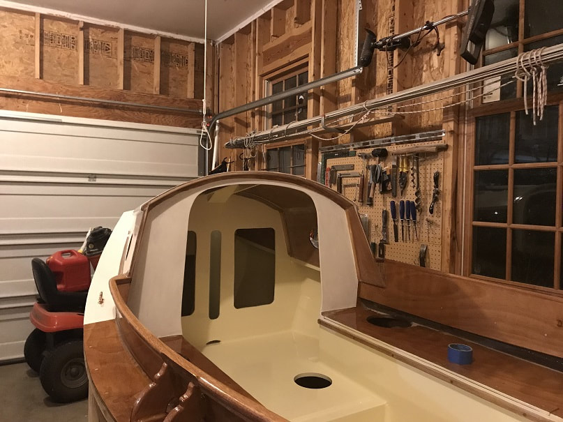
- Sanded and faired the interior cabin and roof fillets and surfaces, when the boat was flipped over. I completed the 3 coats of Pettit EZPoxy with hardener on the cabin interior, when it was flipped over. This included the modified Bulkhead 4.
Painting the veranda interior with the boat flipped over.
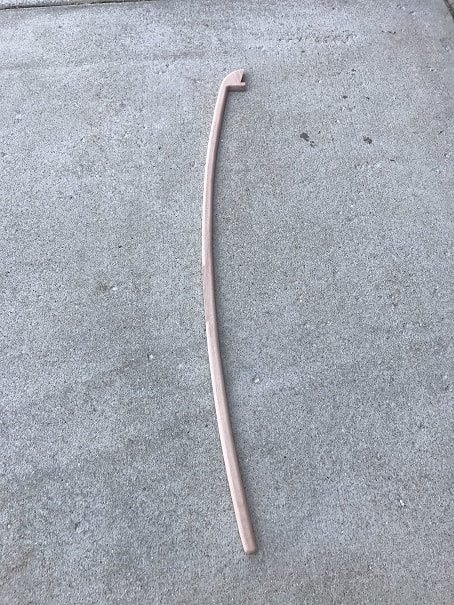
I made 1/4" x 5/8" anti-chafe strips for the fore and aft edges of the roof-top. These are made from clear vertical grain fir. The bend radius was a little tight but I did it without steaming. To play it safe, I carefully and gradually clamped them onto to curved mold over the course of a month and let them sit that way. I started building these a while ago so had time to do that.
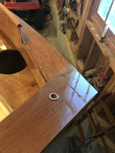
I drilled 3/4" holes into the transom cap, one to starboard, one to port, to accommodate the adjustable mainsheet traveler. These are 3/4" OD, 5/8" ID, 3/4" long, shoulder bushings, made of bronze. I scored the O.D. of the bushings with a file, and epoxied them in place.
.....Mounting hardware to the deck.....
And so we reach the end of this page. At this stage in the build process, I began mounting hardware including cleats, chocks, eyes straps, pad eyes, and such. All this is covered on the Installing SCAMP Hardware Page